242
5 Reedie Drive, 7
th
Floor
Wheaton, MD 20902
240-777-0311 or 311 in Montgomery County
montgomerycountymd.gov/dps
DRY WELL (DW) - Requirements and Guidance Document
Effective September 1, 2021
The
Dry Well methods described in this document are based on the design found in Chapter 5 of the
Maryland Stormwater Design Manual and the ESD Process & Computations Supplement dated July 2010.
Where deemed appropriate, the design specifications have been modified by the Montgomery County
Department of Permitting Services (DPS).
A. Facility Description
A Dry Well is a below ground, excavated pit filled with stone and sand that provides temporary storage of
rooftop runoff within the measure’s void spaces and allows infiltration into the surrounding soils. Rooftop
runoff is directed to the Dry Well via gutters, downspouts and solid underground piping. The runoff is
distributed within the facility via perforated pipe. Dry Wells may only receive runoff from roofs and are not
acceptable for treating runoff from non-rooftop sources such as driveways, decks, patios, trench drains,
surface drainage structures, or sump pumps. Proprietary chamber products are also available for use as
Dry Wells.
B. System Considerations
1. Ap
plicability
Dr
y Wells may be used on projects where groundwater recharge is desired and soil conditions
demonstrate that recharge is achievable. This practice may not be located in existing or
proposed slopes that exceed 15% or where the 4:1 phreatic line extended from the Dry Well’s
bottom intersects a slope that exceeds 15%. A minimum of one foot and a maximum of three
feet of vegetated earth cover must be placed above the stone layer (top of the Dry Well.) A
minimum of 50% of the Dry Well’s storage volume must be located within undisturbed (in-situ)
soils. They cannot be located under impervious surfaces such as driveways, walks, and patios
but the vegetated area over Dry Wells can be incorporated into Disconnection of Non-Rooftop
and/or Rooftop Runoff ESD measures.
2. Soi
ls (Refer to MCDPS “Soil Testing Guidelines for SWM Practices” Document)
Soil testing results must be included with all initial submissions. Acceptable soil testing
methods include soil typing and infiltration testing. For existing single family recorded lots that
are not going through the subdivision process, soil typing is acceptable. The depth from the
bottom of the Dry Well to the groundwater elevation shall be four feet or more, so best
judgement must be used in determining the depths at which to take soil samples. A sufficient
number of samples shall be taken to ensure a representation of the general characteristics of
the soil on the property. If unsuitable conditions such as poor soils, groundwater or rock are
encountered after plan approval and during construction, DPS may collect a review fee and
require a formal plan revision.
3. Set
backs and Shapes
Dr
y Wells shall be setback at least 10 feet from slab on grade structures (such as garages,
homes without basements, and the exposed side of walkout units) and in-ground swimming
pools and at least 15 feet from all other buried foundation structures.

P
age 2 of 5
September 2021
Dry Wells shall be setback a minimum of five feet from water and sewer house connections
and a minimum of three feet from all other utilities unless a greater setback is required by the
utility company. All utilities (for instance water, sewer, gas and electric) must be shown on the
plan so setbacks can be verified.
S
etback requirements apply to items on adjacent properties also. Plans must show structures,
wells, septic, etc. on adjacent properties so required setbacks to off-site improvements can be
verified.
D
ry Wells and outfall pipes may not be placed within any existing or proposed easements
including P.U.E.’s., P.I.E.’s, and other easements adjacent to the public Right-of-Way (ROW).
However, where no adjacent easement is present Dry Wells may be placed directly next to, but
out of, the ROW with no setback. Refer to the DPS Dry Well for Roof Runoff Detail (Dry Well
Detail) for other minimum setback and location requirements. Setbacks to features on adjacent
properties (i.e. structures, wells, septic systems) must also be considered and compliance must
be illustrated on the plan.
W
hile it is preferable to locate Dry Wells down grade of building foundations, it is not a
requirement in all cases. When Dry Wells are upgrade of buildings the designer may choose
to include additional measures in the Dry Well design to discourage lateral flow to foundations.
These measures, such as impermeable liners, must be shown on the plan and a section must
be provided. Impermeable liners must never be placed at the bottom of a Dry Well.
Dry Wells can be an irregular shape but must be buildable using standard equipment and
customary construction practices. They shall not be narrower than two feet at any point or
incorporate any angles less than 45 degrees at any corners.
C. Design Criteria
1. S
izing
ESD vo
lume (ESDv) credit and the associated dry well sizing are directly related to the amount
of roof draining to a Dry Well. The total roof area permitted to drain to any individual Dry Well
is 1,000 sq.ft.
B
ecause of the 1,000 sq.ft. limitation and the relationship between roof area and Dry Well size,
it is essential that the designer use the actual roof square footage in all calculations. Each roof
segment’s flow to a gutter and to a downspout must be feasible. Finally, to ensure the correct
roof segments drain to the specific Dry Well sized to treat them, the design must include the
layout, material, and size of the solid pipe system that collects and conveys runoff from the
downspouts to the Dry Well.
O
nce the total roof area to a Dry Well is established and regardless of the site’s Target P
E
, the
P
E
used to compute the minimum and maximum ESDv is established as 1” and 2.6”
respectively. Volume credit is only given for the actual roof drainage area and P
E
achieved.
Oversizing of Dry Wells beyond the maximum ESDv is not acceptable. When a P
E
of 2.6” is
used to determine a maximum ESDv, and a Dry Well is designed accordingly, all of the ESDv
can be credited towards meeting the project’s overall requirement. This is one acceptable
method that can be used where necessary to meet the treatment requirements for areas that
do not drain to a Dry Well, such as sidewalks, areaways and decks. Note that vehicular areas
should be treated directly wherever practicable to do so, and compensation should only be
used when needed.
Pag
e 3 of 5
September 2021
With the minimum and maximum ESDv known the designer can determine the location, shape
and size (length, width and depth) that will provide the intended volume. ESDv provided in any
Dry Well is a summation of all voids (stone + sand) and chamber volume when applicable. A
void ratio of 40% (0.40) shall be used when computing the available cubic feet of ESDv storage
for stone and sand.
2. Ma
ximum Depth of Storage
The max
imum allowable storage depth within a Dry Well is a function of the desired drawdown
time (48 hours), the soil type’s average infiltration rate and the void ratio within the facility.
These parameters were used to establish the 5-foot maximum allowable depth for a stone
drywell. Proprietary facilities with larger void ratios result in shallower allowable storage depths.
For example, the maximum depth for a structure providing a 95% void ratio would be calculated
as:
0.5
inches per hour X 48 hours = 24 inches or 2 feet
2 feet/.95 = 2.1 feet maximum storage depth
NO
TE: For design purposes 0.5 inches per hour is used as a basis for establishment of
allowable depth requirements. This is a standard calculation and may not be modified.
3. Inflow and Interior Design Criteria
Roof
runoff shall be piped directly from the gutters and downspouts to each Dry Well. It is
acceptable to connect more than one downspout as long as the maximum roof drainage area
to a Dry Well of 1,000 sq. ft. is not exceeded. The downspout must be connected to the Dry
Well by a minimum 4-inch solid schedule 40 PVC pipe. HDPE pipe is not permitted. The use
of standard and readily available fittings and bends is encouraged. When possible there should
be only one point at which the pipe enters the Dry Well. It should enter at 90 degrees to the
side wall of the Dry Well and should be centrally located to maximize runoff distribution.
Th
e initial 6-inches of pipe within the Dry Well must be solid. The interior distribution pipes
must be minimum 4-inch schedule 40 PVC, perforated per the Dry Well Detail. In order to avoid
a joint where the non-perforated and perforated pipes meet inside the Dry Well, it is acceptable
to use one length of pipe where the first 6-inches segment inside the Dry Well is solid and the
required perforations are drilled beyond the solid section. The layout of the interior pipes must
be designed to maximize distribution of runoff within the Dry Well and must also be shown on
the plan. See Example Layouts – Plan View on the Dry Well Detail for further guidance.
Pr
etreatment filtering measures must be utilized to remove debris such as leaves from runoff
prior to entering the Dry Well. In-line filtering, self-cleaning systems that are accessible and
easy to clean shall be incorporated into each downspout draining to a Dry Well. Gutter screens
cannot be used for pretreatment filtering. The system’s design should discourage runoff from
bypassing the Dry Well. The in-line filtering devices to be used must be specified by the
designer and shown on the plans. See the Dry Well Detail for additional information.
4. Ov
erflow Design Criteria
In order to prevent backup of runoff in the downspout during larger storm events an overflow
downspout surcharge pipe must be provided at each downspout that drains to a Dry Well.
Discharge from the downspout surcharge pipe must be directed to a splash pad.
When the potential exists for the conveyance or inflow pipes to be surcharged due to static
head, it may be desirable to add an overflow pipe or pop up emitter to the system. This will

Pag
e 4 of 5
September 2021
always be in addition to the required overflow downspout surcharge pipe. The flow from the
overflow pipe or emitter must be directed to a location on the property where it can continue
to flow in a positive and non-erosive manner without contributing to nuisance drainage
problems such as a wet lawn areas or seepage across sidewalks. If an optional overflow pipe
is incorporated into the design it must be shown on the plan including the outfall location and
invert and cannot conflict with any easements. Pop up emitters, if utilized, must be shown and
the type specified on the plan.
5. Sto
ne
Dry Wells shall be filled with clean 1.5 - 3.0-inch diameter clean stone meeting ASTM D448.
Mirafi-140N or DPS approved equivalent filter fabric shall be placed on the top and sides of
the facility as shown on the Dry Well Detail. Under no circumstances shall geotextile or filter
fabric be allowed to be placed on the bottom of the facility or in any other location other than
those specifically approved on the plan.
6. Sa
nd Bed
A 12-i
nch layer of fine aggregate sand shall be provided at the bottom of the excavation. Clean
ASTM C33 or AASHTO M6 Fine Aggregate Concrete Sand is required per DPS “Sand
Specifications” which must be included on the plan.
7. Ob
servation Well/Clean Out
The D
ry Well must incorporate an Observation Well/Clean Out in accordance with the Dry
Well Detail and the location must be as specified by the designer and shown on the plans.
D. Plan Requirements
1. The f
ollowing Dry Well Detail provides additional guidance and information. It must be placed
on any plan that utilizes a Dry Well however the plan set must also include project
specific information as outlined below. This detail does not take the place of the
required design elements outlined in this document, such as layout of interior
perforated pipe.
2. Min
imum Project specific information to be included on design plans:
• Items required to be shown per this document’s guidance
• Items required per Layout Guidance on the Dry Well Detail
• Existing or proposed easements that may affect Dry Well locations
• Location of primary and alternate well, geothermal wells and septic with minimum setback
• Setback dimensions when placed close to the minimum setback requirement (both on-site
and on adjacent property when applicable)
• Dry Well dimensions including cover above the Dry Well to finished grade. (Can be in table
form) Include cross sections on the plan when necessary. A section is always required if
a liner is proposed.
• A roof drainage plan delineating and quantifying the individual roof segments that drain to
each downspout
• Downspouts, shown, numbered and labelled on the roof drainage plan and on the plan
view
• Pipe system from downspouts to drywells with layout, size, material and other information
required for compliant construction
Dry Well Detail follows.
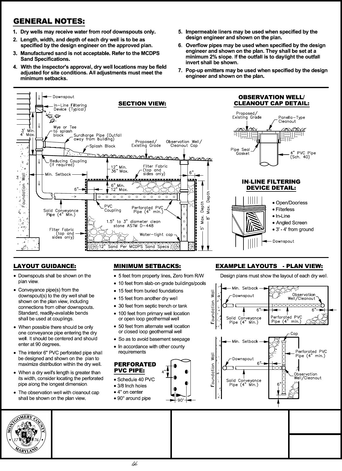
· Downspouts shall be shown on the
plan view.
· Conveyance pipe(s) from the
downspout(s) to the dry well shall be
shown on the plan view, including
connections from other downspouts.
Standard, readily-available bends
shall be used at couplings.
· When possible there should be only
one conveyance pipe entering the dry
well. It should be centered and should
enter at 90 degrees.
· The interior 6" PVC perforated pipe shall
be designed and shown on the plan to
maximize distribution within the dry well.
· When a dry well's length is greater than
its width, consider locating the perforated
pipe along the longest dimension.
· The observation well with cleanout cap
shall be shown on the plan view.
MONTGOMERY COUNTY
DEPARTMENT OF
PERMITTING SERVICES
DATE:
SEPTEMBER 2021
SCALE:
NONE
WATER RESOURCES SECTION
DRY WELL FOR
ROOF RUNOFF
DETAIL
1. Dry wells may receive water from roof downspouts only.
2. Length, width, and depth of each dry well is to be as
specified by the design engineer on the approved plan.
3. Manufactured sand is not acceptable. Refer to the MCDPS
Sand Specifications.
4. With the inspector's approval, dry well locations may be field
adjusted for site conditions. All adjustments must meet the
minimum setbacks.
5. Impermeable liners may be used when specified by the
design engineer and shown on the plan.
6. Overflow pipes may be used when specified by the design
engineer and shown on the plan. They shall be set at a
minimum 2% slope. If the outfall is to daylight the outfall
invert shall be shown.
7. Pop-up emitters may be used when specified by the design
engineer and shown on the plan.
· Schedule 40 PVC
· 3/8 Inch holes
· 4" on center
· 90° around pipe
· 5 feet from property lines, Zero from R/W
· 10 feet from slab-on-grade buildings/pools
· 15 feet from buried foundations
· 15 feet from another dry well
· 30 feet from septic trench or tank
· 100 feet from primary well location
or open loop geothermal well
· 50 feet from alternate well location
or closed loop geothermal well
· So as to avoid basement seepage
· In accordance with other county
requirements
· Open/Doorless
· Filterless
· In-Line
· Angled Screen
· 3' - 4' from ground
Design plans must show the layout of each dry well.
*
*
SECTION VIEW:
OBSERVATION WELL/
CLEANOUT CAP DETAIL:
IN-LINE FILTERING
DEVICE DETAIL:
EXAMPLE LAYOUTS - PLAN VIEW:MINIMUM SETBACKS:LAYOUT GUIDANCE:
PERFORATED
PVC PIPE:
GENERAL NOTES:
Linda Kobylski, Land Development Division Chief
September 1, 2021
