Grandstream Networks, Inc.
GWN7000
Enterprise Multi-WAN Gigabit VPN Router
User Manual

P a g e | 2
GWN7000 User Manual
Version 1.0.9.6
COPYRIGHT
©2020 Grandstream Networks, Inc. http://www.grandstream.com
All rights reserved. Information in this document is subject to change without notice. Reproduction or
transmittal of the entire or any part, in any form or by any means, electronic or print, for any purpose
without the express written permission of Grandstream Networks, Inc. is not permitted.
The latest electronic version of this guide is available for download here:
http://www.grandstream.com/support
Grandstream is a registered trademark and Grandstream logo is trademark of Grandstream Networks, Inc.
in the United States, Europe and other countries.
OPEN SOURCE LICENSES
GWN7000 firmware contains third-party open source software. Grandstream Open source licenses can be
downloaded from Grandstream web site from here
CAUTION
Changes or modifications to this product not expressly approved by Grandstream, or operation of this
product in any way other than as detailed by this guide, could void your manufacturer warranty.
WARNING
Please do not use a different power adaptor with devices as it may cause damage to the products and void
the manufacturer warranty.

P a g e | 3
GWN7000 User Manual
Version 1.0.9.6
Table of Contents
DOCUMENT PURPOSE ............................................................................................... 13
CHANGE LOG .............................................................................................................. 14
Firmware Version 1.0.9.6 ..................................................................................................................... 14
Firmware Version 1.0.9.5 ..................................................................................................................... 14
Firmware Version 1.0.9.4 ..................................................................................................................... 14
Firmware Version 1.0.6.32 ................................................................................................................... 14
Firmware Version 1.0.6.28 ................................................................................................................... 14
Firmware Version 1.0.4.23 ................................................................................................................... 15
Firmware Version 1.0.4.20 ................................................................................................................... 15
Firmware Version 1.0.2.75 ................................................................................................................... 15
Firmware Version 1.0.2.71 ................................................................................................................... 16
WELCOME ................................................................................................................... 17
PRODUCT OVERVIEW ................................................................................................ 18
Technical Specifications ....................................................................................................................... 18
INSTALLATION ............................................................................................................ 20
Equipment Packaging .......................................................................................................................... 20
Connect your GWN7000 ...................................................................................................................... 20
Safety Compliances ............................................................................................................................. 21
Warranty ............................................................................................................................................... 21
GETTING STARTED ..................................................................................................... 22
LED Indicators ..................................................................................................................................... 22
Use the WEB GUI ................................................................................................................................ 22
Access WEB GUI .......................................................................................................................... 22
WEB GUI Languages ................................................................................................................... 25
WEB GUI Configuration ................................................................................................................ 25
Overview Page ............................................................................................................................. 26

P a g e | 4
GWN7000 User Manual
Version 1.0.9.6
Save and Apply Changes ............................................................................................................. 28
ROUTER CONFIGURATION ........................................................................................ 29
Status ................................................................................................................................................... 29
Router Configuration ............................................................................................................................ 30
WAN Ports Settings ...................................................................................................................... 30
Additional WAN Port ..................................................................................................................... 31
NET Port ....................................................................................................................................... 32
Tunnel ........................................................................................................................................... 32
Global Settings ............................................................................................................................. 34
Switch Configuration ............................................................................................................................ 34
LAN ............................................................................................................................................... 34
Static DHCP .................................................................................................................................. 37
Switch ........................................................................................................................................... 37
QoS ...................................................................................................................................................... 39
DDNS ................................................................................................................................................... 44
DPI ....................................................................................................................................................... 45
ROUTING ...................................................................................................................... 47
Static Routes ........................................................................................................................................ 47
Policy Routing ...................................................................................................................................... 49
Feature Overview ......................................................................................................................... 49
Creating/Configuring Routing Policies .......................................................................................... 49
Using Routing Policies .................................................................................................................. 51
SETTING UP A WIRELESS NETWORK ...................................................................... 55
Discover and Pair GWN76xx Access Points ....................................................................................... 55
Access Point Location.......................................................................................................................... 58
Client Bridge ........................................................................................................................................ 58
Transfer AP .......................................................................................................................................... 59
SSIDs ................................................................................................................................................... 59
Mesh Network ...................................................................................................................................... 66

P a g e | 5
GWN7000 User Manual
Version 1.0.9.6
Upgrading Access Points ..................................................................................................................... 68
Single Access Point upgrade ........................................................................................................ 68
Sequential Upgrade ...................................................................................................................... 68
CLIENTS CONFIGURATION ........................................................................................ 70
Clients .................................................................................................................................................. 70
Status ............................................................................................................................................ 71
Edit IP and Name .......................................................................................................................... 72
Bandwidth Rules ........................................................................................................................... 72
Block a Client ................................................................................................................................ 73
Clients Access ...................................................................................................................................... 74
Time Policy ........................................................................................................................................... 75
Banned Clients ..................................................................................................................................... 76
VPN (VIRTUAL PRIVATE NETWORK) ......................................................................... 77
Overview .............................................................................................................................................. 77
OpenVPN® Server Configuration ........................................................................................................ 77
Generate Self-Issued Certificate Authority (CA) ........................................................................... 77
Generate Server/Client Certificates .............................................................................................. 80
Create OpenVPN® Server ........................................................................................................... 87
OpenVPN® Client Configuration ......................................................................................................... 91
L2TP/IPSEC Configuration .................................................................................................................. 96
GWN7000 L2TP/IPSec Client Configuration ................................................................................ 96
PPTP CONFIGURATION ..................................................................................................................... 99
GWN7000 Client Configuration .................................................................................................... 99
GWN7000 PPTP Server Configuration ...................................................................................... 101
IPSec VPN Tunnel ............................................................................................................................. 104
Overview ..................................................................................................................................... 104
Configuring GWN7000 IPSec Tunnel ......................................................................................... 105
FIREWALL .................................................................................................................. 112
Basic Settings .................................................................................................................................... 112

P a g e | 6
GWN7000 User Manual
Version 1.0.9.6
General Settings ......................................................................................................................... 112
Port Forwarding .......................................................................................................................... 113
DMZ ............................................................................................................................................ 114
UPnP .......................................................................................................................................... 114
Traffic Rules Settings ......................................................................................................................... 115
Input ............................................................................................................................................ 115
Output ......................................................................................................................................... 117
Firewall Advanced Settings ................................................................................................................ 120
General Settings ......................................................................................................................... 120
SNAT ........................................................................................................................................... 120
DNAT .......................................................................................................................................... 121
CAPTIVE PORTAL ..................................................................................................... 123
Guest.................................................................................................................................................. 123
Policy List ........................................................................................................................................... 124
Internal Splash Page .................................................................................................................. 125
External Splash Page ................................................................................................................. 128
Splash Page ....................................................................................................................................... 130
Vouchers ............................................................................................................................................ 131
Voucher Feature Description ...................................................................................................... 131
Voucher Configuration ................................................................................................................ 131
Using Voucher with GWN Captive Portal ................................................................................... 134
BANDWIDTH RULES ................................................................................................. 136
WEBSITE BLOCKING ................................................................................................ 138
Create Blackhole Policy ..................................................................................................................... 138
Assign Blackhole Policy to Network Groups ...................................................................................... 139
Assign Blackhole Policy to Clients ..................................................................................................... 140
MAINTENANCE AND TROUBLESHOOTING ............................................................ 143
Maintenance ...................................................................................................................................... 143
Basic ........................................................................................................................................... 143

P a g e | 7
GWN7000 User Manual
Version 1.0.9.6
Upgrade ...................................................................................................................................... 144
Access ........................................................................................................................................ 144
Syslog ......................................................................................................................................... 145
Logserver .................................................................................................................................... 145
Debug ................................................................................................................................................ 146
Capture ....................................................................................................................................... 147
Ping/Traceroute .......................................................................................................................... 148
Syslog ......................................................................................................................................... 149
Connection Table ........................................................................................................................ 150
Email/Notification ............................................................................................................................... 151
Schedule ............................................................................................................................................ 154
LED .................................................................................................................................................... 156
File Sharing ........................................................................................................................................ 157
SNMP ................................................................................................................................................. 159
User Manager .................................................................................................................................... 161
UPGRADING AND PROVISIONING .......................................................................... 162
Upgrading Firmware .......................................................................................................................... 162
Upgrading via WEB GUI ............................................................................................................. 162
Provisioning and backup .................................................................................................................... 163
Download Configuration ............................................................................................................. 163
Configuration Server ................................................................................................................... 163
Reset and Reboot .............................................................................................................................. 163
EXPERIENCING THE GWN7000 ENTERPRISE ROUTER ....................................... 164

P a g e | 8
GWN7000 User Manual
Version 1.0.9.6
Table of Tables
Table 1: GWN7000 Technical Specifications .............................................................................................. 18
Table 2: GWN7000 Equipment Packaging .................................................................................................. 20
Table 3: LED Indicators ............................................................................................................................... 22
Table 4: Overview ........................................................................................................................................ 27
Table 5: GWN7000 WEB GUI→Router→WAN→WAN Port (1,2) ............................................................... 30
Table 6: NET Port ........................................................................................................................................ 32
Table 7: 6In4 Tunnels .................................................................................................................................. 32
Table 8: 6rd Tunnels .................................................................................................................................... 32
Table 9: AICCU Tunnels .............................................................................................................................. 33
Table 10: GRE Tunnels ............................................................................................................................... 33
Table 11: GWN7000 WEB GUI→Router→Port→Global Settings ............................................................... 34
Table 12: LAN Group Options ..................................................................................................................... 35
Table 13: Port Mirroring ............................................................................................................................... 38
Table 14: General Settings .......................................................................................................................... 40
Table 15: Legacy QoS Settings ................................................................................................................... 42
Table 16: QoS Policy Manager (acc) .......................................................................................................... 43
Table 17: DPI Settings ................................................................................................................................. 46
Table 18: IPv4 Static Routes ....................................................................................................................... 47
Table 19: IPv6 Static Routes ....................................................................................................................... 48
Table 20: Create Policy Members ............................................................................................................... 50
Table 21: Device Configuration ................................................................................................................... 56
Table 22: Wi-Fi ............................................................................................................................................ 60
Table 23: Wi-Fi ............................................................................................................................................ 68
Table 24: Time Policy Parameters .............................................................................................................. 75
Table 25: CA Certificate ............................................................................................................................... 78
Table 26: Server Certificate ......................................................................................................................... 81
Table 27: Client Certificate .......................................................................................................................... 85
Table 28: OpenVPN® Server ...................................................................................................................... 89
Table 29: OpenVPN® Client ....................................................................................................................... 94
Table 30: L2TP Configuration ...................................................................................................................... 97
Table 31: PPTP Configuration ................................................................................................................... 100
Table 32: PPTP Server Configuration Parameters ................................................................................... 102
Table 33: IPSec Phase 1 Parameters ....................................................................................................... 107
Table 34: IPSec Phase 2 Parameters ....................................................................................................... 110
Table 35: Port Forward .............................................................................................................................. 113
Table 36: DMZ ........................................................................................................................................... 114
Table 37: UPnP Settings ........................................................................................................................... 115
Table 38: Firewall Traffic Rules ................................................................................................................. 119
Table 39: Firewall-General Settings .......................................................................................................... 120

P a g e | 9
GWN7000 User Manual
Version 1.0.9.6
Table 40: SNAT ......................................................................................................................................... 120
Table 41: DNAT ......................................................................................................................................... 122
Table 42: Captive Portal – Policy List – Splash Page is “Internal” ............................................................ 126
Table 43: Captive Portal – Policy List – Splash Page is “External” ........................................................... 128
Table 44: Voucher Parameters .................................................................................................................. 133
Table 45: Bandwidth Rules........................................................................................................................ 136
Table 46: Maintenance - Basic .................................................................................................................. 143
Table 47: Maintenance - Upgrade ............................................................................................................. 144
Table 48: Maintenance - Access ............................................................................................................... 144
Table 49: Maintenance - Syslog ................................................................................................................ 145
Table 50: Debug-Capture .......................................................................................................................... 147
Table 51: Email Setting ............................................................................................................................. 152
Table 52: Email Events .............................................................................................................................. 153
Table 53: LEDs .......................................................................................................................................... 156
Table 54: Add a New File to Share ............................................................................................................ 158
Table 55: SNMP Basic Page ..................................................................................................................... 159
Table 56: SNMP Advanced Page .............................................................................................................. 160
Table 57: VPN User Parameters ............................................................................................................... 161
Table 58: Network Upgrade Configuration ................................................................................................ 162

P a g e | 10
GWN7000 User Manual
Version 1.0.9.6
Table of Figures
Figure 1: GWN7000 Front View .................................................................................................................. 20
Figure 2: GWN7000 Back View .................................................................................................................. 21
Figure 3: GWN7000 Web GUI Login Page ................................................................................................. 23
Figure 4: Change Password on first boot .................................................................................................... 24
Figure 5: Setup Wizard ............................................................................................................................... 24
Figure 6: GWN7000 Web GUI Language ................................................................................................... 25
Figure 7: GWN7000 Web GUI Language ................................................................................................... 25
Figure 8: Overview Page ............................................................................................................................. 26
Figure 9: Apply Changes ............................................................................................................................. 28
Figure 10: Router's Status .......................................................................................................................... 29
Figure 11: LAN Groups ............................................................................................................................... 34
Figure 12: Add/Edit a LAN Group ............................................................................................................... 35
Figure 13 : DHCP Binding ........................................................................................................................... 37
Figure 14: Static DHCP Devices List .......................................................................................................... 37
Figure 15 : Custom Port VLAN Mapping ..................................................................................................... 38
Figure 16: QoS ............................................................................................................................................ 39
Figure 17: DPI Status .................................................................................................................................. 46
Figure 18: Routes ........................................................................................................................................ 48
Figure 19: Create a New Member ............................................................................................................... 50
Figure 20: Create New Routing Policy ........................................................................................................ 51
Figure 21: Members list ............................................................................................................................... 52
Figure 22: Policies List ................................................................................................................................ 52
Figure 23: LAN Routing Policy .................................................................................................................... 53
Figure 24: Configuring Firewall Rule using Route Policy ............................................................................ 54
Figure 25: Discover AP ............................................................................................................................... 55
Figure 26: Discovered Devices ................................................................................................................... 56
Figure 27: GWN7610 online........................................................................................................................ 56
Figure 28: Locating Access Points .............................................................................................................. 58
Figure 29: Client Bridge .............................................................................................................................. 59
Figure 30: SSID ........................................................................................................................................... 59
Figure 31: Add a new SSID ......................................................................................................................... 60
Figure 32: Device Membership ................................................................................................................... 65
Figure 33: Access Points Status ................................................................................................................. 67
Figure 34: Mesh Settings ............................................................................................................................ 67
Figure 35: Sequential Upgrade - Choosing Multiple Devices ..................................................................... 69
Figure 36: All-at-Once and Sequential Upgrade ......................................................................................... 69
Figure 37: Clients ........................................................................................................................................ 70
Figure 38: Clients - Select Items ................................................................................................................. 71
Figure 39: Client's Status ............................................................................................................................ 72

P a g e | 11
GWN7000 User Manual
Version 1.0.9.6
Figure 40: Client's Configuration ................................................................................................................. 72
Figure 41: Client Bandwidth Rules .............................................................................................................. 73
Figure 42: Block a Client ............................................................................................................................. 73
Figure 43: Unban Client .............................................................................................................................. 73
Figure 44: Global Blacklist .......................................................................................................................... 74
Figure 45: Managing the Global Blacklist ................................................................................................... 74
Figure 46: Adding a MAC Access List ......................................................................................................... 74
Figure 47: Blacklist Access List ................................................................................................................... 75
Figure 48: Ban/Unban Client ....................................................................................................................... 76
Figure 49: Create CA Certificate ................................................................................................................. 78
Figure 50: CA Certificate ............................................................................................................................. 80
Figure 51: Generate Server Certificates ..................................................................................................... 81
Figure 52: User Management ..................................................................................................................... 83
Figure 53: Client Certificate......................................................................................................................... 85
Figure 54: Create OpenVPN® Server ......................................................................................................... 88
Figure 55: OpenVPN® ................................................................................................................................ 91
Figure 56: OpenVPN® Client ...................................................................................................................... 93
Figure 57: OpenVPN® Client ...................................................................................................................... 96
Figure 58: L2TP Client Configuration .......................................................................................................... 97
Figure 59: L2TP Client ................................................................................................................................ 99
Figure 60: PPTP Client Configuration ....................................................................................................... 100
Figure 61: PPTP Client ............................................................................................................................. 101
Figure 62: PPTP Server Configuration ..................................................................................................... 102
Figure 63: Branch Office IPSec Phase 1 Configuration ............................................................................ 107
Figure 64:Branch Router IPSec Phase 2 Configuration ........................................................................... 109
Figure 65: HQ Router IPSec Phase 2 Configuration ................................................................................ 110
Figure 66: Basic → General Settings ........................................................................................................ 112
Figure 67: Port Forward ............................................................................................................................ 113
Figure 68: DMZ ......................................................................................................................................... 114
Figure 69: INPUT Rule Sample................................................................................................................. 116
Figure 70: Output Rules Sample ............................................................................................................... 118
Figure 71: Traffic Rules Settings ............................................................................................................... 119
Figure 72: Captive Portal – Guest Page ................................................................................................... 123
Figure 73: Captive Portal - Guest Page - Select Items ............................................................................. 123
Figure 74: Captive Portal - Policy List ....................................................................................................... 124
Figure 75: Add a New Policy ..................................................................................................................... 125
Figure 76: Authentication rules ................................................................................................................. 129
Figure 77: Captive Portal – Splash Page .................................................................................................. 130
Figure 78: Add Voucher Sample ............................................................................................................... 132
Figure 79: Vouchers List ........................................................................................................................... 133
Figure 80: Captive Portal with Voucher authentication ............................................................................. 135
Figure 81: MAC Address Bandwidth Rule ................................................................................................. 137

P a g e | 12
GWN7000 User Manual
Version 1.0.9.6
Figure 82: Bandwidth Rules ...................................................................................................................... 137
Figure 83: Create Blackhole Policy ........................................................................................................... 138
Figure 84: Blackhole Policy List ................................................................................................................ 139
Figure 85: Network Group Blackhole ........................................................................................................ 140
Figure 86: Clients ACL .............................................................................................................................. 141
Figure 87: Client Blackhole Configuration ................................................................................................. 142
Figure 88: Logserver Configuration .......................................................................................................... 146
Figure 89: Capture Files ............................................................................................................................ 147
Figure 90: IP Ping ..................................................................................................................................... 148
Figure 91: Traceroute ................................................................................................................................ 149
Figure 92: Syslog ...................................................................................................................................... 150
Figure 93: Connection Table ..................................................................................................................... 151
Figure 94: Email settings ........................................................................................................................... 152
Figure 95: Notification ............................................................................................................................... 153
Figure 96: Create New Schedule .............................................................................................................. 155
Figure 97: Schedules List .......................................................................................................................... 156
Figure 98: LED Scheduling Sample .......................................................................................................... 157
Figure 99: Add a New File to Share .......................................................................................................... 158
Figure 100: File Share Actions .................................................................................................................. 158
Figure 101: Access File Share .................................................................................................................. 159

P a g e | 13
GWN7000 User Manual
Version 1.0.9.6
DOCUMENT PURPOSE
This document describes how to configure the GWN7000 to manage wired and wireless networks via an
intuitive WebGUI. The intended audiences of this document are network administrators. Please visit
http://www.grandstream.com/support to download the latest “GWN7000 User Manual”.
This guide covers following topics:
• Product Overview
• Installation
• Getting Started
• Router Configuration
• Routing
• Setting up a Wireless Network
• Clients Configuration
• VPN
• Firewall
• Captive Portal
• Voucher
• Bandwidth Rules
• Website Blocking
• Maintenance and Troubleshooting
• Upgrading and Provisioning
• Experiencing the GWN7000 Enterprise Router

P a g e | 14
GWN7000 User Manual
Version 1.0.9.6
CHANGE LOG
This section documents significant changes from previous versions of the GWN7000 user manuals. Only
major new features or major document updates are listed here. Minor updates for corrections or editing are
not documented here.
Firmware Version 1.0.9.6
• No major change.
Firmware Version 1.0.9.5
• Added support for TLS 1.2.
Firmware Version 1.0.9.4
• Updated the Email/Notification configuration page. [Email/Notification]
• Updated the Mesh Configuration page. [Mesh Network]
• Added configuration support of External Captive Portal Support as Linkyfi, Purple, and Universal
Platform. [External Splash Page]
• Enhanced Wi-Fi Service by adding configurable options of [Beacon Interval], [DTIM Period], and
[Multicast to Unicast].
• Enhanced Bandwidth Rules by adding option to limit bandwidth Per-Client. [Range Constraint]
• Added support of ARP Proxy. [ARP Proxy]
• Enhanced Client Information. [CLIENTS CONFIGURATION]
• Enhanced Captive Portal features. [Failsafe Mode] [Enable Daily Limit] [Force to Follow]
Firmware Version 1.0.6.32
• Important security fix applied.
Firmware Version 1.0.6.28
• Added support for static DHCP binding. [Static DHCP]
• Added date time display on Overview Page. [Overview Page]
• Added Support for custom port mapping in port mirroring. [Switch]
• Added support for policy routing. [Policy Routing]
• Split Network Group configuration into VLAN and SSID. [LAN][SSIDs]
• Added ability to select wan ports on static routes. [Static Routes]
• Added Support for Mesh Network. [Mesh Network]
• Added support for scheduling feature. [Schedule]
• Improved Schedule settings. [Schedule]

P a g e | 15
GWN7000 User Manual
Version 1.0.9.6
• Enhanced QoS features (ACC). [QoS]
• Added support for Vouchers feature. [Vouchers]
• Added possibility to print/delete multiple vouchers. [Vouchers]
• Added expiration period to vouchers. [Vouchers]
• Added support for Transfer AP. [Transfer AP]
• Added support for new methods of authentication in captive portal. [CAPTIVE PORTAL]
• Added support for post/pre-authentication rules on captive portal. [CAPTIVE PORTAL]
• Added option to select from which interface issue the ping/traceroute utilities. [Ping/Traceroute]
• Added option to notify admin if the wan port is down.
• Added support for IPsec VPN tunnels. [IPSec VPN Tunnel]
• Added Support for MTU configuration on WAN ports. [MTU]
• Added Support for sequential Upgrade [Sequential Upgrade]
• Added support for GRE Tunnels. [Tunnel]
• Added PPP Keep Alive option for PPTP VPN Server. [PPP Keep-Alive Interval]
• Added option to set MTU/MRU for PPTP VPN Server. [MTU] [MRU]
• Added “Flush Connection Reload” option under Firewall settings. [Flush Connection Reload]
• Added support for more syslog levels configuration. [Syslog]
• Added option to set NET port as WAN port [NET Port]
• Added support for additional WAN ports. [Additional WAN Port]
• Added DNS rebind attack protection. [Rebind Protection]
Firmware Version 1.0.4.23
• Added support for enable/disable MPPE in both PPTP server and client. [MPPE]
Firmware Version 1.0.4.20
• Added support for Additional Routed Subnets. [Additional IPv4 Addresses][Destination IP]
• Added support for Timed Client Disconnect and Enhanced Client Blocking. [Clients Access]
• Added support for Client Bridge (GWN76xx Access Point is required for this feature.). [Client
Bridge]
• Added support for OpenApp ID for Deep Packet Inspection. [DPI]
• Added support for Syslog Server. [Logserver]
• Added support for PPTP Server. [PPTP CONFIGURATION]
• Added support for Smart Queue QoS. [QoS]
• Added support for Configurable web UI access port.[Web WAN Access][Web HTTP Access][Web
HTTPS Port]
• Added support for E-mail notifications. [Email/Notification]
Firmware Version 1.0.2.75
• Added support for Captive Portal [CAPTIVE PORTAL]
• Added support for Bandwidth Rules [BANDWIDTH RULES]

P a g e | 16
GWN7000 User Manual
Version 1.0.9.6
• Added support for Select Band per SSID [SSID Band]
• Added support for selectively enable 802.11b/g/n [Mode]
• Added option to enable/disable support for 802.11b devices [Allow Legacy Device(802.11b)]
• Added support for custom wireless power [Custom Wireless Power(dBm)]
• Added support for AP location using blinking LED [Access Point Location]
• Added support for limit client count per SSID. [SSIDs]
• Added support for better roaming decision [SSIDs]
• Added support for LEDs schedule [LED]
• Added support for Wi-Fi schedule [SSIDs]
• Added option to enable/disable DHCP option 66 & 43 override [Allow DHCP options 66 and 43
override]
Firmware Version 1.0.2.71
• This is the initial version.

P a g e | 17
GWN7000 User Manual
Version 1.0.9.6
WELCOME
Thank you for purchasing Grandstream GWN7000 Enterprise Multi-WAN Gigabit VPN Router.
The GWN7000 is a powerful enterprise-grade multi-WAN Gigabit VPN router. Ideal for the enterprise,
small-to-medium business, retail, education, hospitality and medical markets, the GWN7000 supports
comprehensive Wi-Fi network management software and VPN solutions that can be shared across one or
many different physical locations. It features high-performance routing and switching power and a
hardware-accelerated VPN client/server for secure inter-office connectivity. To maximize network reliability,
the GWN7000 supports traffic load balancing and failover. The GWN7000 features an integrated controller
and automated provisioning master that can setup and manage up to 300+ in-network GWN series Wi-Fi
Access Points. This can be easily operated through the product’s intuitive web browser user interface,
which also offers a central panel to monitor and control the entire network.
--------------------------------------------------------------------------------------------------------------------------------------------
Caution:
Changes or modifications to this product not expressly approved by Grandstream, or operation of this
product in any way other than as detailed by this User Manual, could void your manufacturer warranty.
Warning:
Please do not use a different power adaptor with the GWN7000 as it may cause damage to the products
and void the manufacturer warranty.
--------------------------------------------------------------------------------------------------------------------------------------------
P a g e | 18
GWN7000 User Manual
Version 1.0.9.6
PRODUCT OVERVIEW
Technical Specifications
Table 1: GWN7000 Technical Specifications
Network Interfaces
• 2 x autosensing 10/100/1000 WAN Ports
• 1 x autosensing 10/100/1000 NET port configurable as LAN, WAN or
VoIP port
• 4 x autosensing 10/100/1000 LAN Ports
WAN
• DHCP Client
• Static IP
• PPPoE
• Load balance & failover
• Rule based routing
LAN
• DHCP server
• DNS Cache
• Multiple zones
• VLAN tagging
Auxiliary Ports
• 2 x USB 3.0 ports
• 1 x Reset Pinhole
Routing
Performance
• Up to 1 million packets/second with 64-byte packet size
USB
• Printer sharing
• File sharing
Network Protocols
• IPv4, IPv6, 802.1Q, 802.1p
VPN
• Protocols: PPTP, L2TP/IPSec, OpenVPN®
• Client, Server or pass through
LED
• 8 green-color LEDs for device tracking and status indication
Mounting
• Indoor wall mount
• Desktop
QoS
• VLAN, ToS, supports multiple traffic classes, filter by port, IP address,
DSCP, and policing.
Firewall
• NAT, DMZ, Port Forwarding, SPI, UPnP
P a g e | 19
GWN7000 User Manual
Version 1.0.9.6
Auto Provisioning
Capability
• Embedded provisioning controller to manage up to 300+ GWN series
Wi-Fi Access Points
Management
• Web, CLI
Power
• 802.3at PoE (To power the unit via LAN1 port)
• Included Power Supply: 12V/2A
• Max power consumption: 16W
Environmental
• Operation: 0°C to 50°C
• Storage: -10°C to 60°C
• Humidity: 10% to 90% Non-condensing
Physical
• Unit Dimensions: 200 x 136 x 37mm; Unit Weight: 570g
• Entire Package Dimensions: 324 x 163.5 x 54mm, Entire Package
Weight: 930g
Package Content
• GWN7000 Enterprise Router
• 12V/2A Power Adapter
• Quick Installation Guide
• GPL License
Compliance
• FCC, CE, RCM, IC
P a g e | 20
GWN7000 User Manual
Version 1.0.9.6
INSTALLATION
Before deploying and configuring the GWN7000, the device needs to be properly powered up and
connected to the network. This section describes detailed information on installation, connection and
warranty policy of the GWN7000.
Equipment Packaging
Table 2: GWN7000 Equipment Packaging
Main Case
Yes (1)
Power adaptor
Yes (1)
Quick Installation Guide
Yes (1)
GPL License
Yes (1)
Connect your GWN7000
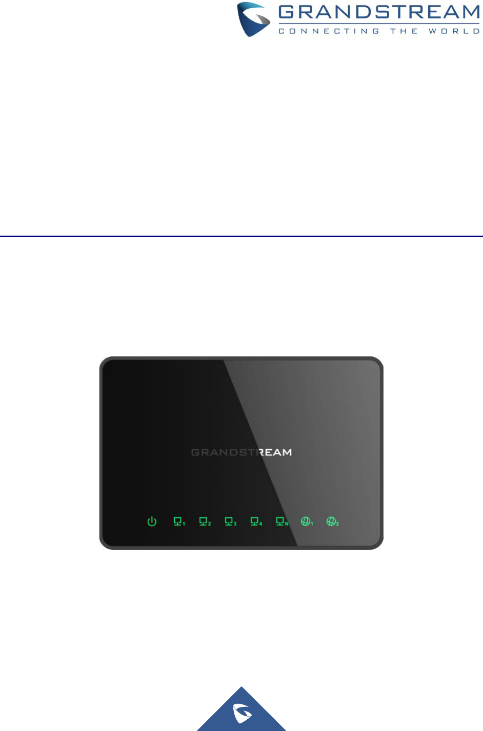
Figure 1: GWN7000 Front View

P a g e | 21
GWN7000 User Manual
Version 1.0.9.6
Figure 2: GWN7000 Back View
To set up the GWN7000, follow the steps below:
1. Connect one end of an RJ-45 Ethernet cable into the WAN1 or/and WAN2 port(s) of the
GWN7000.
2. Connect the other end of the Ethernet cable(s) into a DSL modem or router(s) as an uplink to ISP.
3. Connect the 12V DC power adapter into the power jack on the back of the GWN7000. Insert the
main plug of the power adapter into a surge-protected power outlet.
4. Wait for the GWN7000 to boot up and connect to internet/network. In the front of the GWN7000
the Power LED will be in solid green, and the WAN LED will flash in green indicating data
transmission.
5. Connect one of the LAN ports to your computer, the associated LED ports will flash in green.
6. (Optional) Connect LAN port(s) to your LAN, including GWN76XX access points and other devices,
the associated LED port(s) will flash in green.
Safety Compliances
The GWN7000 Enterprise Router complies with FCC/CE and various safety standards. The GWN7000
power adapter is compliant with the UL standard. Use the universal power adapter provided with the
GWN7000 package only. The manufacturer’s warranty does not cover damages to the device caused by
unsupported power adapters.
Warranty
If the GWN7000 Enterprise Router was purchased from a reseller, please contact the company where the
device was purchased for replacement, repair or refund. If the device was purchased directly from
Grandstream, contact our Technical Support Team for an RMA (Return Materials Authorization) number
before the product is returned. Grandstream reserves the right to remedy warranty policy without prior
notification.
P a g e | 22
GWN7000 User Manual
Version 1.0.9.6
GETTING STARTED
The GWN7000 Enterprise Router provides an intuitive web GUI configuration interface for easy
management to give users access to all the configurations and options for the GWN7000’s setup.
This section provides step-by-step instructions on how to read LED indicators and use Web GUI interface
of the GWN7000.
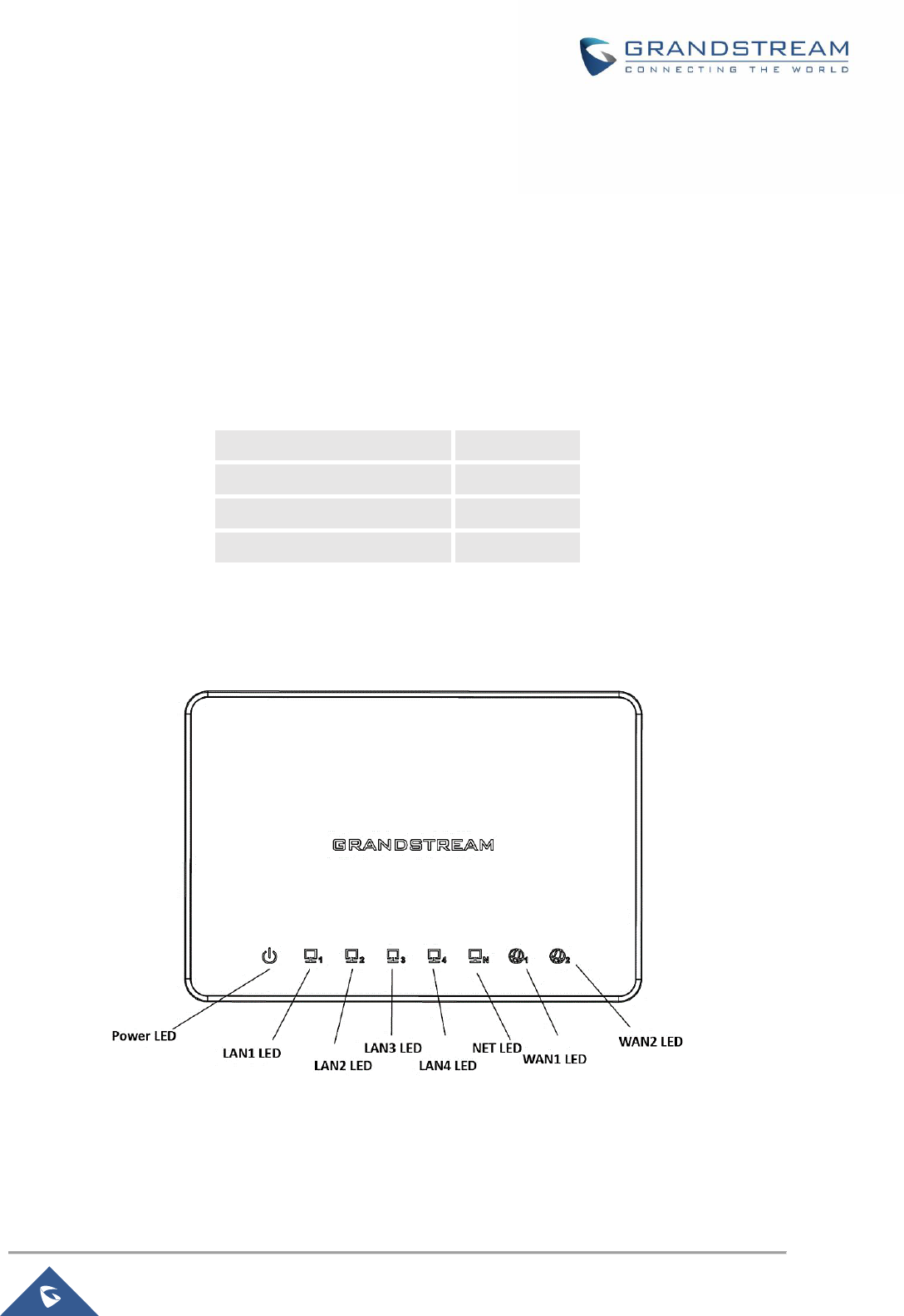
LED Indicators
The front panel of the GWN7000 has LED indicators for power and interfaces activities, the table below
describes the LED indicators status.
Table 3: LED Indicators
LED
Status
Indication
POWER
OFF
GWN7000 is powered off or abnormal power supply.
Solid green
GWN7000 is powered on correctly.
WAN (1,2)
Flashing green
GWN7000 is connected as a client to another network and
data is transferring.
Solid green
GWN7000 is connected as a client to another network and
there is no activity.
LAN (1,2,3,4,5)
Flashing green
A device is connected to the corresponding LAN port and
data is transferring.
Solid green
A device is connected to the corresponding LAN port and
there is no activity.
Use the WEB GUI
Access WEB GUI
The GWN7000 embedded Web server responds to HTTPS GET/POST requests. Embedded HTML pages
allow users to configure the device through a Web browser such as Microsoft IE, Mozilla Firefox, Google
Chrome.
P a g e | 23
GWN7000 User Manual
Version 1.0.9.6
Figure 3: GWN7000 Web GUI Login Page
To access the Web GUI:
1. Connect a computer to a LAN Port of the GWN7000.
2. Ensure the device is properly powered up, and the Power, LAN port LEDs light up in green.
3. Open a Web browser on the computer and enter the web GUI URL in the following format:
https://192.168.1.1 (Default IP address).
4. Enter the administrator’s login and password to access the Web Configuration Menu. The default
administrator's username and password are "admin" and "admin".
Note: At first boot or after factory reset, users will be asked to change the default administrator and user
passwords before accessing GWN7000 web interface.
The password field is case sensitive with a maximum length of 32 characters. Using strong password
including letters, digits and special characters is recommended for security purposes.
P a g e | 24
GWN7000 User Manual
Version 1.0.9.6
Figure 4: Change Password on first boot
At first login, a Setup Wizard tool will pop up to help going through the configuration setup, or exit to
configure manually. Setup Wizard can be accessed anytime by clicking on while on the web
interface.
Figure 5: Setup Wizard
P a g e | 25
GWN7000 User Manual
Version 1.0.9.6
WEB GUI Languages
Currently the GWN7000 series web GUI supports English and Simplified Chinese.
To change default language, select the displayed language at the upper right of the web GUI either before
or after logging in.
Figure 6: GWN7000 Web GUI Language
Figure 7: GWN7000 Web GUI Language
WEB GUI Configuration
GWN7000 web GUI includes 8 main sections to configure and manage the router and check connection
status.
• Overview: Provides an overall view of the GWN7000’s information presented in a Dashboard style for
easy monitoring.
• Router: Displays device’s status and used to configure ports settings such as IP configuration for
WAN ports, load balancing, failover, static routes, switch port mirroring, QoS and DDNS.
• Routing: Gives the admin the possibility to configure static routing and policy-based routing.
• Access Points: To add, pair and manage discovered access points.
• SSIDs: To add and manage wireless network SSIDs using paired access points via VLANs.
P a g e | 26
GWN7000 User Manual
Version 1.0.9.6
• Clients: Shows and manages the list of the clients connected to LAN ports of the GWN7000 and
wireless clients connected via GWN76xx access points.
• VPN: Configures OpenVPN® Client/Server, PPTP, IPSec and L2TP/IPSec client tunnels.
• Firewall: Basic and advanced Firewall configuration to securely manage router’s incoming/outgoing
traffic.
• Captive Portal: Configuration settings for the captive portal feature.
• Bandwidth Rules: Configures the bandwidths rules that allows users to limit bandwidth utilization per
SSID or client (MAC address or IP address).
• System Settings: For Maintenance and debugging features, as well as generating certificates and
file sharing.
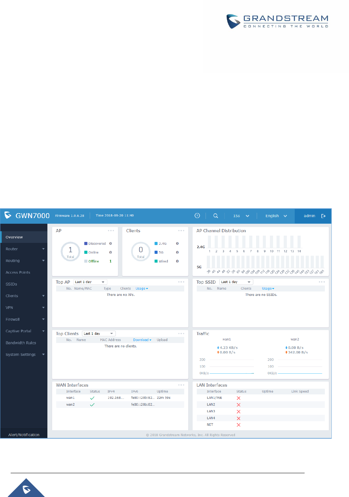
Overview Page
Overview is the first page shown after successful login to the GWN7000’s Web Interface. It provides an
overall view of the GWN7000’s information presented in a Dashboard style for easy monitoring.
Figure 8: Overview Page

P a g e | 27
GWN7000 User Manual
Version 1.0.9.6
It is used to show the status of the GWN7000 for different items, please refer to the following table for each
item:
Table 4: Overview
AP
Shows the number of Access Points that are Discovered, Paired
(Online) and Offline. Click on to go to Access Points’ page for
basic and advanced configuration options for the APs
Clients
Shows the total number of connected clients, and a count for clients
connected to each Channel. Click on to go to Clients page for
more options.
AP Channel Distribution
Shows the Channel used for all APs that are paired with this Access
Point.
Top AP
Shows the Top APs list, assort the list by number of clients connected
to each AP or data usage combining upload and download. Click on
to go to Access Points page for basic and advanced
configuration options for the APs.
Top SSID
Shows the Top SSIDs list, assort the list by number of clients
connected to each SSID or data usage combining upload and
download. Click on to go to SSID page for more options.
Top Clients
Shows the Top Clients list, assort the list of clients by their upload or
download. Click on to go to Clients page for more options.
Traffic
Shows the sent/received traffic data speeds on both WAN ports.
WAN Interfaces
Shows the status of the wan interfaces (IP, Uptime, status …etc).
LAN Interfaces
Displays the status of the LAN interfaces, which includes also the NET
port.
This will display the connection status, the uptime, and the link speeds.
Note that Overview page in addition to other tabs can be updated each 15s, 1min, 2min, 5min or Never by
clicking in the upper bar menu (Default is 15s).
P a g e | 28
GWN7000 User Manual
Version 1.0.9.6
Save and Apply Changes
When clicking on "Save" button after configuring or changing any option on the web GUI pages. A
message mentioning the number of changes will appear on the upper menu.
Figure 9: Apply Changes
Click on button to apply changes, or to undo the changes.
The router will reload all necessary services in order to for the changes to take effect.
P a g e | 29
GWN7000 User Manual
Version 1.0.9.6
ROUTER CONFIGURATION
This section includes configuration pages for network WAN ports, LAN ports, QoS, DDNS, DPI and shows
also the router status.
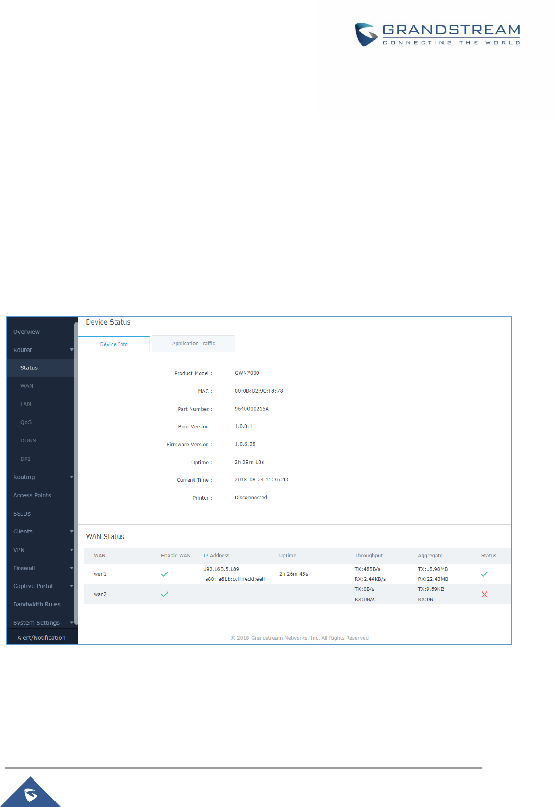
Status
Status page displays Device Status to check MAC address, Part Number, Firmware related information
and Uptime for the GWN7000; and WAN Status showing general information about WAN Ports such as
uptime, current throughput, aggregate usage, and IP address and also the application traffic.
Router’s Status page can be accessed from Web GUI → Router → Status.
Figure 10: Router's Status
Note: Once DPI is enabled under Router feature. Users will be able to see their application traffics under
Application Traffic section.

P a g e | 30
GWN7000 User Manual
Version 1.0.9.6
Router Configuration
Connect to GWN7000’s Web GUI from a computer connected to a LAN port and go to Router→WAN page
for Port configuration.
WAN Ports Settings
The GWN7000 has 2 WAN ports configured as DHCP clients by default. Each port can be connected with
DSL modem or routers. WAN ports support also setting static IPv4/IPv6 addresses and configure PPPoE
for each WAN port. Please refer to the following table for basic network configuration parameters on WAN
ports for GWN7000.
Table 5: GWN7000 WEB GUI→Router→WAN→WAN Port (1,2)
Enabled
Choose whether to enable or disable the WAN port.
Name
Specify the port name.
WAN Address Type
Select "DHCP", "Static" or "PPPoE" mode on the WAN interfaces of GWN7000.
The default setting is "DHCP".
• DHCP
When selected, it will act as a DHCP client and acquire an IPv4 address
automatically from the DHCP server.
• Static
When selected, the user should set a static IPv4 address, IPv4 Subnet Mask,
IPv4 Gateway and adding Additional IPv4 Addresses as well to
communicate with the web interface, SSH, or other services running on the
device.
• PPPoE
When selected, the user should set the PPPoE account and password,
PPPoE Keep alive interval and Inter-Key Timeout (in seconds).
Preferred IPv4 DNS
Enter the preferred DNS server address (IPv4 address). If Preferred DNS is set,
GWN7000 will use it in priority.
Alternate IPv4 DNS
Enter the Alternate DNS server address (IPv4 address). If Preferred DNS is set,
GWN7000 will use it in when the Preferred DNS fails.
Tracking IP
Configures the tracking IP(s). ICMP packets are being used to track the IP(s)
address(es). When the tracking fails, the GWN7000 will use the secondary WAN
port as failover. Default IP used is 8.8.8.8.
MTU
Configures the maximum transmission unit allowed on the wan port. The valid
range is 64-9000 Bytes, and the default value is 1500.

P a g e | 31
GWN7000 User Manual
Version 1.0.9.6
Native IPv6
Used to enable assigning IPv6 address to GWN7000. Once checked users will be
able to configure following fields: “IPv6 Address Assignment”, “Preferred IPv6
DNS”, “Alternate IPv6 DNS” and “IPv6 Relay to LAN”.
IPv6 Address
Assignment
This option is appearing when enabling “Native IPv6” option.
Select "Auto" to get an IPv6 address from DHCP server or "Static" to configure
manually an IPv6 address. If set to Static, the following fields should be
configured:
• IPv6 Address/Prefix Length
Used to set an IPv6 address/Prefix length when using Static IPv6 option
Example: fec0:470:28:5b2::1/64
• IPv6 Gateway
Used to define the Gateway’s IPv6 address.
• IPv6 Prefix/IPv6 Prefix Length
Enter the IPv6 prefix and IPv6 prefix length.
Example: ::1/64
Preferred IPv6 DNS
This option appears only when “Native IPv6” option is enabled.
It is used to set a preferred DNS server address (IPv6 address). If Preferred DNS
is set, GWN7000 will use it in priority.
Alternate IPv6 DNS
This option appears only when “Native IPv6” option is enabled.
It is used to set an Alternate DNS server address (IPv6 address). If Preferred DNS
is set, GWN7000 will use it in when the Preferred DNS fails.
IPv6 Relay to LAN
This option appears only when “Native IPv6” option is enabled.
When enabled the GWN7000 will relay IPv6 address to LAN clients
VLAN Tagging
Used to enable VLAN tagging. If set to “0” the VLAN tagging will be disabled,
otherwise set a VLAN value between 2 and 4093. Default is 0.
Additional WAN Port
Users have the ability to create virtual wan interfaces that would be mapped with a specific physical wan
port (either WAN1 or 2 or NET port when configured as WAN port) and use VLAN tags for each additional
wan port.
Note: There is a limit of 15 wan ports to be supported including physical and logical wan ports.
Go under “Router → WAN→ Additional WAN Port” to add a logical wan port and the attach it to a
physical interface. As for the configuration parameters please refer to Table 5: GWN7000 WEB
GUI
→
Router
→
WAN
→
WAN Port (1,2).

P a g e | 32
GWN7000 User Manual
Version 1.0.9.6
NET Port
This page allows for the configuration of NET port, which can be used either as LAN port or WAN port.
Below are the available options to configure the NET port.
Table 6: NET Port
Enable LAN1 (NET
Port)
Enable the NET port as a normal LAN port.
Enable WAN (Net
Port)
Enable the NET port as a WAN port, and set the required configuration as WAN1
and 2. See Table 5: GWN7000 WEB GUI
→
Router
→
WAN
→
WAN Port (1,2)
Tunnel
Tunnel page is used to set IPv6 tunnels on WAN ports via IPv6 tunnel brokers service providers, this
serves the purpose of transferring IPv6 packets over IPv4 Network. It supports creating 6in4, 6rd, AICCU
and GRE tunnels. Please refer to below tables for each tunnel type.
Table 7: 6In4 Tunnels
WAN Interface
Choose the WAN port on which to setup the 6in4 tunnel.
MTU
Set the Maximum Transmission Unit value.
The valid range is 64-9000. Default value is 1500.
6in4 IPv4 Peer
Address
Enter the IPv4 tunnel endpoint at the tunnel’s provider.
6in4 Tunnel Endpoint
IPv6 Address
Enter the local IPv6 address delegated to the tunnel endpoint.
Example: 2001:db8:2222::2/64
6in4 Routed Prefix
Set the routable prefix given by the tunnel provider to allow LAN clients to get
addresses from that prefix.
Tunnel ID
Specifies the tunnel’s ID.
Username
Set the username used to login into the tunnel broker.
Password
Set the password (used for endpoint update).
Update Key
Set the update key, it overrides the password used for endpoint update.
Table 8: 6rd Tunnels
WAN Interface
Choose the WAN port on which to setup the 6rd tunnel.
MTU
Set the Maximum Transmission Unit value.
The valid range is 64-9000 and default value is 1500.

P a g e | 33
GWN7000 User Manual
Version 1.0.9.6
6rd IPv4 Peer
Address
Enter the IPv4 Peer address.
6rd IPv6 Address
Prefix
Specifies the IPv6 prefix given by the provider.
Example: 2001:B000::/32
IPv6 Prefix Length
Specifies the IPv6 prefix length (Value between 1 and 128).
Example: 32
IPv4 Prefix Length
Specifies the prefix length of the IPv4 transport address.
(Value between 1 and 32).
Table 9: AICCU Tunnels
WAN Interface
Choose the WAN port on which to setup the aiccu tunnel.
Username
Enter the Username (Provided by signing up with SixXS Tunnel Broker)
Password
Enter the Username’s password
Table 10: GRE Tunnels
WAN Interface
Specifies the WAN interface to bind the tunnel to.
Name
Set a name for the tunnel connection.
Enabled
Enabled/Disable the tunnel connection.
GRE Peer IP Address
Specifies the tunnel destination address (public IP).
GRE Tunnel IP
Address
Specify the local GRE tunnel interface. (ex: 10.1.1.2)
GRE Tunnel Netmask
Set the Tunnel interface netmask. (ex: 255.255.255.0)
MTU
Configures the maximum transmission unit. The valid range is 64-9000 and the
default is 1500.
Subnet
Set the destination subnet that is reachable though GRE tunnel.
IP Masquerading
Enable/Disable IP masquerading. Users could configure this option under the
“General” tab of Firewall → Advanced as well.
Tunnel Input Key
Specifies the key that would be added to the incoming packets.
Tunnel Output Key
Specifies the key that would be added to the outgoing packets.
P a g e | 34
GWN7000 User Manual
Version 1.0.9.6
Global Settings
This section specifies operating mode for multi-WAN that will be used for enabling/disabling Failover and
Load Balancing on WAN ports and using MAC override address.
The following table shows the configuration parameters for global WAN settings
Table 11: GWN7000 WEB GUI→Router→Port→Global Settings
Local Routing Policy
Specifies the routing policy that would be applied on locally generated traffic
from the GWN7000 router. See [Policy Routing] section.
MAC Override
Address
This option is used to override the MAC address of the GWN7000 Router.
MAC Address octets (in hex) are separated by “:” in English input condition. The
characters here must be lowercase.
Note: Reboot the router to take effect.
Switch Configuration
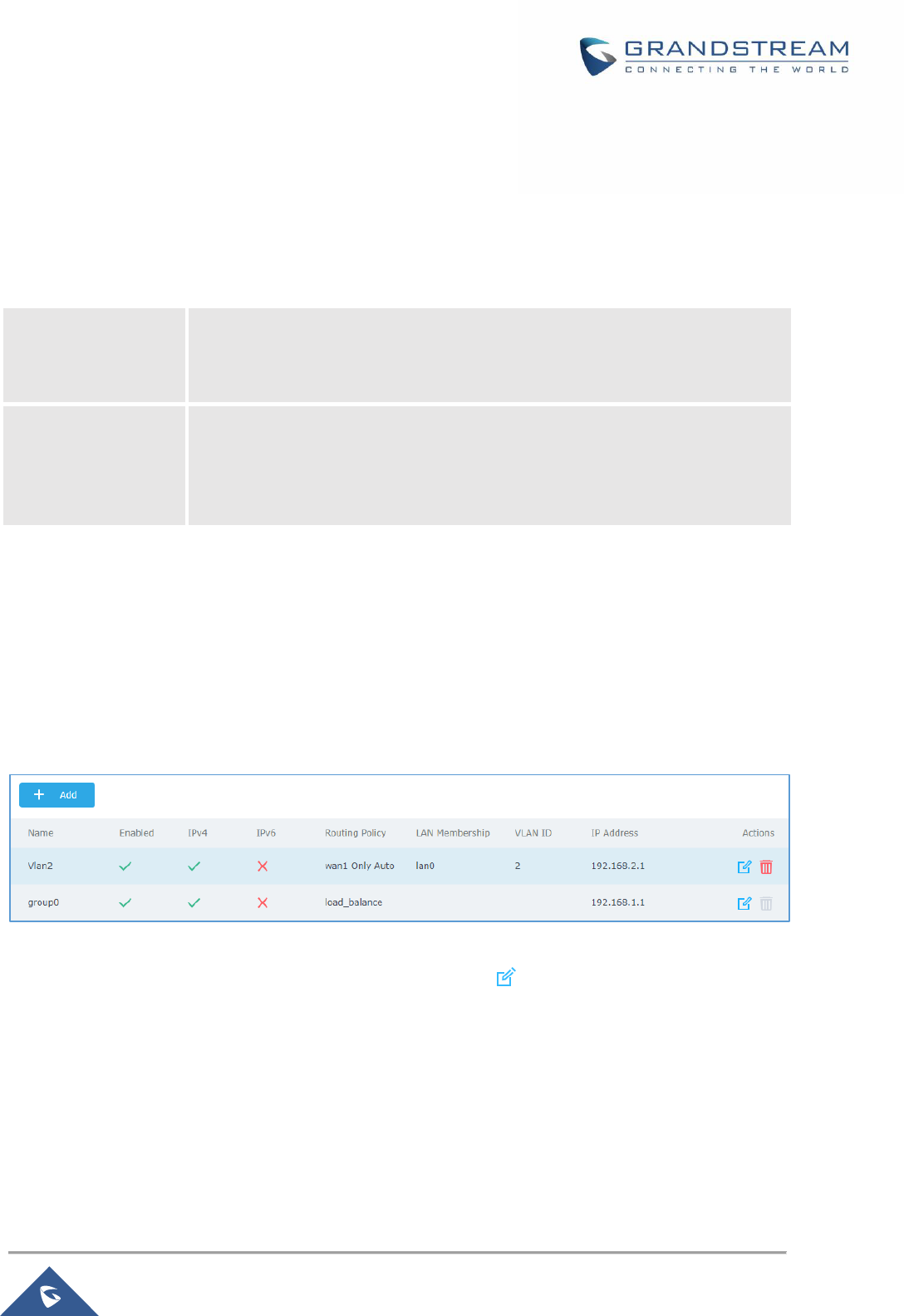
LAN
GWN7000 supports creating up to 16 different LAN groups separated as VLANs with the possibility to add
and pair GWN76xx Access Points to each LAN which is mapped to an SSID by VLAN tagging.
To access LAN configuration page, log in to the GWN7000 WebGUI and go to Router → LAN.
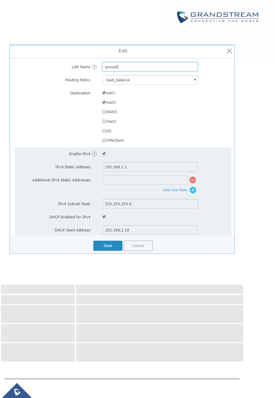
Figure 11: LAN Groups
The GWN7000 will have a default group named group0, click on to edit it, or click on “Add” to add a
new LAN subnet.
P a g e | 35
GWN7000 User Manual
Version 1.0.9.6
Figure 12: Add/Edit a LAN Group
Following table gives description for the parameters available to configure LAN groups:
Table 12: LAN Group Options
LAN Name
Specifies the name for the LAN group.
Enabled
Check to activate the newly created LAN group.
Routing Policy
Select which routing to use for this LAN network. See Policy Routing
section for more details.
Destination
If enabled, choose which groups you want to forward, if not, you can
manually configure the forward rules under firewall settings.
LAN Membership
Configure the LAN port membership. If choose lan1 (NET Port), please
make sure you have enabled lan1 under Router→ WAN→ NET port Tab.
P a g e | 36
GWN7000 User Manual
Version 1.0.9.6
VLAN
Check to enable VLAN. This field is appearing only when having more
than one LAN subnet.
VLAN ID
Set a VLAN ID. Valid range is between 2 and 4093.
Enable IPv4
Check to enable IPv4 addressing for this LAN.
Ipv4 Static Address
Set a static Ipv4 address for the LAN subnet when enabling Ipv4.
Additional IPv4 Static
Address
Set an additional static Ipv4 address for the LAN subnet when enabling
IPv4.
Ipv4 Subnet Mask
Set the Subnet Mask.
DHCP Enabled for Ipv4
Check to enable DHCP using Ipv4. This will allow clients connected to
this LAN subnet to get Ipv4 addresses automatically from GWN7000
acting as DHCP server.
DHCP Start Address
Set the starting Ipv4 address for this LAN’s clients.
DHCP End Address
Set the ending Ipv4 address for this LAN’s clients
DHCP Lease Time
Set the lease time for DHCP clients, the value can be defined in hours,
minutes, or as “infinite”. Default lease time is “12h”.
DHCP Options
Set the DHCP options. Click on to add another option, and to
delete an option.
Example: 44,192.168.2.50 for DHCP option 44 and 192.168.2.50 is the
WINS server’s address. Please refer to the following link for DHCP
options syntax: https://wiki.openwrt.org/doc/howto/dhcp.dnsmasq
DHCP Gateway
Defines the IP address of the DHCP gateway.
DHCP Preferred DNS
Set the preferred DNS Servers via DHCP.
DHCP Alternate DNS
Set the alternate DNS Servers via DHCP.
DHCPv4 Relay Enabled
Enable this option, if you want the GWN7000 relays the DHCP requests
from clients to another DHCP server(s). Once checked, click to add
another DHCPv4 Relay Target, and to delete a DHCPv4 Relay
Target.
Enable IPv6
Check to enable IPv6 addressing for this LAN subnet.
IPv6 Relay from WAN
Check to allow GWN7000 to relay IPv6 DHCP request from LAN’s clients
to WAN port.
DHCP Enabled for IPv6
Check weather to enable IPv6 DHCP server for this LAN.
IPv6 Prefix for Assignment
Set the prefix value to be assigned to the LAN. Valid range is between 1
to 64. Example: 64 will assign /64 prefixes.
IPv6 Subnet Hint
Set the subnet mask value.
P a g e | 37
GWN7000 User Manual
Version 1.0.9.6
IPv6 Uplink
Select the WAN port.
Static DHCP
Users can use the feature in order to set static DHCP binding to certain clients, to whom you do not want
the IP address to change.
In order to configure Static DHCP, please follow below steps:
1- Go under the menu “Router → LAN → Static DHCP”.
2- Click button to create a new entry.
3- Enter the name of the device, along with its MAC address and IP address.
Figure 13 : DHCP Binding
4- Press Save and Apply to submit the changes.
Figure 14: Static DHCP Devices List
Switch
Under switch configuration menu, admin users can enable port mirroring and the GWN7000 will send a
copy of all network packets seen on one LAN port to another port, where the packet can be analyzed.
Refer to the below table for the available fields to configure.
Also, users can have flexibility in configuring the mapping for each LAN port to have 802.1q VLAN tags
included or excluded from Ethernet frames sent out by the port, in case the tag is needed users can simply
enable it by editing the option custom port mapping.
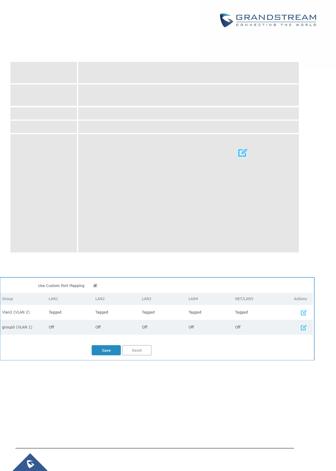
P a g e | 38
GWN7000 User Manual
Version 1.0.9.6
Table 13: Port Mirroring
Enable Outgoing
Mirroring
Check to enable outgoing mirroring for a LAN port. Default is “Disabled”
Enable Incoming
Mirroring
Check to enable incoming mirroring for a LAN port. Default is “Disabled”
Mirroring Port
Select which LAN port that will be mirroring traffic. Default is “Disabled”
Mirrored Port
Select which LAN port that will act as mirrored port. Default is “Disabled”
Use Custom Port
Mapping
Use this option in order to enable VLAN tagging on the ports or disable it or block
the port from participating in the selected VLAN, click on button to change
the settings.
Three options are available for each port:
• Tagged: the port will participate on the VLAN and will tag the outgoing
frames with the 802.1q VLAN id.
• Untagged: The port will participate on the VLAN but will not tag outgoing
frames.
• Off: The port will not participate on the VLAN.
Figure 15 : Custom Port VLAN Mapping
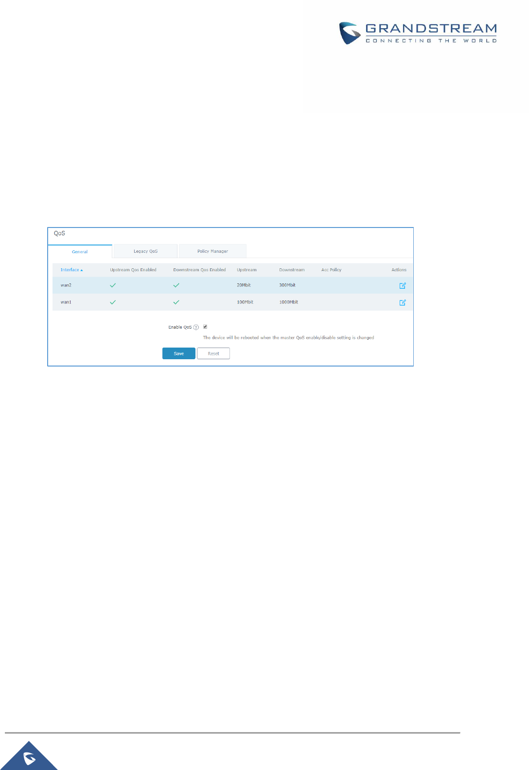
P a g e | 39
GWN7000 User Manual
Version 1.0.9.6
QoS
The GWN7000 offers the possibility to enable and configure QoS on WAN interfaces, this will help to
manage in more depth the network traffic to define priority and classify different services and protocols in
an efficient manner.
Also, the GWN provides the capabilities to configure advanced QoS features such as Active Congestion
Control (ACC) in order to avoid bottleneck on the network, especially when using VoIP.
Figure 16: QoS
To activate QoS, check “Enable QoS” option. Three tabs are available for configuration:
• General: Download and upload bandwidth speeds settings on each WAN interface as well as setting
the smart queue parameters which will allow to select the queuing mode on each wan interface. The
smart queue is an integrated network system that performs better per-packet/per flow network
scheduling, reduces the buffer bloat and keeps latency at acceptable levels. The users can from this
menu select which QoS mode to use on each WAN interface (either ACC, SQM or Legacy QoS).
• Legacy QoS: Legacy QoS allows creating Traffic Classes to prioritize traffic for specific resources on
the network by controlling transmission/upload rate. Note that different classes can be created and
assigned as Traffic filters by respecting following conditions:
✓ The total of Upstream bandwidth values of each created class should not exceed the
upstream bandwidth value configured in General.
✓ The remaining bandwidth will be lent to the next priority level of class.
✓ All filter options are summed together.
✓ While Upstream QoS is dealing with traffic transmission, Policer is controlling the incoming
traffic. Thus, allowing to create rules to specific targets to set priority and received traffic rate,
giving the GWN the ability to drop the exceeding traffic when reaching the max rate.

P a g e | 40
GWN7000 User Manual
Version 1.0.9.6
• Policy Manager: On this menu the user can configure multiple QoS policies in order to apply them on
the WAN interface when selecting QoS type as ACC (Adaptive Congestion Control), this feature
combines the power of the original legacy class based QoS, while adding true ingress shaping, and
reducing the configuration difficulty. Traditional QoS systems rely on the actual bandwidth provided by
the ISP to remain constant, they also require you to set the link rate below what the ISP provisions
your link, which leaves the link underutilized. The ACC QoS solves this problem. The ACC QoS also
features the anti-buffer bloat and flow fairness of the Smart Queue QoS. Beyond that, the new QoS
allows for defining classes so that flows that are latency sensitive and/or need a minimum amount of
bandwidth can be placed int, this is extremely useful for VoIP traffic.
Refer to the following tables for each tab option:
Table 14: General Settings
Up/Down Stream
QoS Enabled
Check to enable upstream and downstream bandwidth speeds for the selected
WAN interface.
Upstream
Set the Upstream value to specify the upload bandwidth for selected interface, the
value should end with Mbit. Note that the set value will affect and limit the
bandwidth values on created classes on QoS Upstream.
Examples: 500Mbit
100Kbit
Downstream
Set the Downstream value to specify the download bandwidth speed for selected
interface, the value should end with “Mbit”, “Kbit” or with no unit if the set value is
referring to “bit” unit.
Examples: 1000Mbit
100Kbit
Type
Select which QoS method to apply on select WAN interface:
• SQM: Smart queue management queueing mode will be applied to the
interface along with the option to select Qdisc and Manager values.
• ACC: Select this option in order to use active congestion control QoS mode
on the interface then select which policy to apply, users should create policies
under “Router→QoS→Policy Manager”.
• Legacy: Select this option in order to use legacy classifying and filter QoS
mode, users need to configure the related DSCP marking and bandwidth
limitations under the menu “Router→QoS→Legacy QoS”.

P a g e | 41
GWN7000 User Manual
Version 1.0.9.6
Qdisc
Select which Queuing discipline method to use for QoS:
• fq_codel (Fair Queue with Controlled Delay)
• Cake
Manager
Choose the type of the smart queue management:
❑ If fq_codel queuing discipline method is selected.
• simple: Three-tier prioritization system.
• simplest: HTB (Hierarchical Token Bucket) shaper with a single fq_codel
queuing discipline.
• simplest_tbf: TBF (Token Bucket Filter) shaper with a single fq_codel
queuing discipline.
❑ If cake queuing discipline method is selected.
• layer_cake: Three-tier prioritization system with cake as a replacement
for HTB rate limiting.
• Piece_of_cake: Single queue with cake as a replacement for HTB rate
limiting.
Link-layer Adaptation
Select the link-layer type for the WAN connection. This can be used to
compensate for the link-layer overhead of certain types of WAN connections.
• None (default).
• Ethernet (should be selected for VDSL connections).
• ATM (should be selected for ADSL connections).
Overhead
If the link-layer is set to something other than “none”, then the link-layer overhead
setting can be used to specify how many bytes of overhead there are.
Defaults are 8 for Ethernet, and 44 for ATM.
Advanced Qdisc
Options
Check this option in order to show advanced Qdisc options to be used.
Squash DSCP on
ingress
Select whether to squash or not the DSCP on ingress packets. By default, this
option is disabled.
Ignore DSCP on
ingress
Select whether to ignore DSCP on ingress packets or not. By default, this option is
disabled.
ECN Status on
Inbound packets
Select whether to set or not ECN status on inbound packets.
ECN Status on
outbound packets
Select whether to set or not ECN status on bound packets.

P a g e | 42
GWN7000 User Manual
Version 1.0.9.6
ACC Policy
Select from the drop-down list the acc policy to apply, policies can be managed
from the Policy Manager tab.
This field appears only when Type is set to “acc”.
Use Active
Congestion
Controller
This Option must be enabled when using ACC (Adaptive Congestion Control)
QoS type under the selected wan interface.
This field appears only when Type is set to “acc”.
Use Custom ping
target
Enter the IPv4 address of the target where the router will send ICM echo
messages to track the health of the link (RTT measurements…etc).
This field appears only when Type is set to “acc”.
Target ping time limit
(ms)
Value that indicates the congestion on the ISP link, this is automatically calculated
on the back end of the router, but users can override it.
This field appears only when Type is set to “acc”.
Table 15: Legacy QoS Settings
Traffic Class
Name
Define a name for the traffic class.
Priority
Set the priority of the traffic class, the lower the value, the highest the priority.
Valid range is between 1 and 64.
Interface
Select the WAN interface from which the traffic will be classified, make sure to
enable the desired interface it from in order to appear.
Upstream
Set Upstream bandwidth value. The value should end with “Mbit”, “Kbit”.
Note that the sum of created classes should have upstream bandwidth speeds
lower than the Upstream bandwidth value configured on QoS Basic.
Examples: 100Mbit
100Kbit
Traffic Filter
Class
Select a class from created traffic classes using drop-down menu.
Name
Define a Name for the traffic filter rule.
DSCP
Choose the Differentiated Services Code Point (DSCP) value from drop-down list.
Default is 0.
IP Source Address
Specify the Source IP address from which the traffic filter rule will be applied.
IP Destination
Address
Specify the Destination IP address to which the traffic filter rule will be applied.
TCP Source Port
Specify the TCP Source port from which the traffic filter rule will be applied.
TCP Destination Port
Specify the TCP Source port to which the traffic filter rule will be applied.
P a g e | 43
GWN7000 User Manual
Version 1.0.9.6
UDP Source Port
Specify the UDP Source port from which the traffic filter rule will be applied.
UDP Destination Port
Specify the UDP Source port to which the traffic filter rule will be applied.
Group Source
Choose the LAN group of the specified Source IP address. If no Source IP
address has been defined, the rule will be applied to all members of that LAN
group.
Policer
Name
Define a Name for the Policer rule.
Interface
Select an interface from which the traffic will be policed, make sure to enable the
desired interface from General QoS in order to appear.
Priority
Set the priority of the traffic class, the lower the value, the highest the priority.
Valid range is between 1 and 64.
Rate
Set a Rate value for download bandwidth when applying policer rule.
DSCP
Choose the Differentiated Services Code Point (DSCP) value from drop-down list.
Default is 0.
IP Source Address
Specify the Source IP address from which the policer rule will be applied.
IP Destination
Address
Specify the Destination IP address to which the policer rule will be applied.
TCP Source Port
Specify the TCP Source port from which the policer rule will be applied.
TCP Destination Port
Specify the TCP Source port to which the policer rule will be applied.
UDP Source Port
Specify the UDP Source port from which the policer rule will be applied.
UDP Destination Port
Specify the UDP Source port to which the policer rule will be applied.
Group Source
Choose the LAN group of the specified Source IP address.
If no Source IP address has been defined, the rule will be applied to all members
of that LAN group.
Table 16: QoS Policy Manager (acc)
General
Name
Define a name for the traffic policy which can be then select on general tab
settings if settings the QoS type for a wan interface to acc (adaptive congestion
control).
Upload/Download → Policy Class
Name
Set a name for the traffic class.
Bandwidth share %
Configure the bandwidth share percentage for this class of traffic, the acc
mechanism will dynamically borrow bandwidth from other classes if one class
needs more, thus using efficiently the available bandwidth.

P a g e | 44
GWN7000 User Manual
Version 1.0.9.6
Set minimum
bandwidth
Enable this option to set the Minimum bandwidth for this traffic class.
Min bandwidth
Configure the minimum bandwidth reserved for this traffic class in Mbps or Kbps.
Set maximum
bandwidth
Enable this option to set the Maximum bandwidth for this traffic class.
Max bandwidth
Configure the maximum bandwidth allowed for this traffic class in Mbps or Kbps.
Minimize RTT (Only
for Download Class)
Enable this option in order to minimize traffic latency/delay → Useful for VoIP.
Upload/Download → Policy Rule
Name
Enter a name for the traffic rule ➔ rules are used to put a traffic into a class.
Enabled
Used to enable/disable the traffic rule.
Protocol
Select the protocol for the traffic rule (TCP, UDP, TCP/UDP or ICMP).
Src IP
Set the source IP of the traffic to be matched.
Src Port
Set the source port number of the traffic to be matched.
Dest IP
Set the destination IP of the traffic to be matched.
Dest Port
Set the destination port number of the traffic to be matched.
Min Pkt Size
Configures the minimum packet size of the traffic that will be matched.
Max Pkt Size
Configures the minimum packet size of the traffic that will be matched.
Class
Select from the drop-down list the class where this traffic will be put, thus making
all necessary bandwidth reservations for this traffic in respect of the configurations
set under the class settings.
DDNS
DDNS allows accessing GWN7000 via domain name instead of IP address, the GWN7000 supports
following DDNS providers:
• Dyndns.org
• Changeip.com
• Zoneedit.com
• Freedns.afraid.org
• He.Net
• Dnsomatic.Com
• No-ip.pl
• Myonlineportal.net
• No-ip.com

P a g e | 45
GWN7000 User Manual
Version 1.0.9.6
Before configuring DDNS settings on the GWN7000, make sure first to create and confirm the DDNS
account via supported providers.
Following steps illustrates how to configure the DDNS settings on your GWN7000:
1. Access to GWN7000 web GUI, and navigate to Router→DDNS, and enable DDNS service.
2. Fill in the domain name created with DDNS provider under Domain Name field.
3. Enter your account username and password under Username and Password fields.
4. Specify the WAN interface to which DDNS is applied under Network interface field.
5. (Optional) For advanced configuration, it is also possible log to Syslog and modify the values of
refreshing fields so to check periodically the updated IP address.
DPI
DPI stands for Deep Packet Inspection which is an option that allows the GWN7000 to analyze the core of
the packet to collect and report information at the Application-layer, such as traffic volume of an application
used by the host.
Snort OpenApp ID allows the System Administrator to view the internet traffic of users. The GUI displays
traffic data in a human-readable format, such as 'Streaming MP4 & Netflix - 31% of total traffic usage.' The
data is accompanied by a graph.
GWN7000 is using Snort for packet inspection and displays traffic status under Status→Application
Traffic as shown on the figure below.
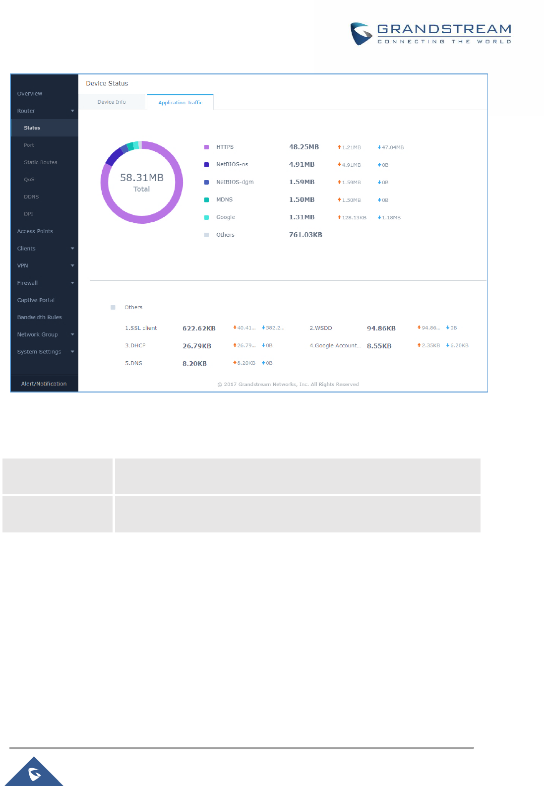
P a g e | 46
GWN7000 User Manual
Version 1.0.9.6
Figure 17: DPI Status
The following table contains the description of the DPI configuration settings.
Table 17: DPI Settings
Enable Application
Tracking
Enables the application tracking. By default, it’s disabled.
Interface
Select the interface on which the application tracking will be performed. By
default, it’s WAN Port 1.
Note: A reboot is required after enabling Depp packet inspection in order for the feature to take effect.
P a g e | 47
GWN7000 User Manual
Version 1.0.9.6
ROUTING
Static Routes
GWN7000 supports setting manually static IPv4 and IPv6 routes as well as displaying routing table entries.
Static routes configuration page can be accessed from GWN7000 WebGUI→Router→Static Routes:
Three tabs are available:
- Routes to view routing table entries.
- IPv4 to create, edit or delete static IPv4 static routes.
- IPv6 to create, edit or delete static IPv6 static routes.
Following actions are available in both IPv4 and IPv6 tabs:
• To add a new static route, click on
• To edit a static route, click on
• To delete a static route, click on
Refer to the following tables when editing or creating IPv4/IPv6 static routes:
Table 18: IPv4 Static Routes
Name
Enter the Name of the static route to be configured.
Enabled
Select whether to enable or disable this static route.
Interface
Choose the LAN network or WAN port, which will be using this static route.
Target Network/Host
Enter the Network/Host IP address on which to route the traffic to.
Example: 192.168.5.0
Netmask
Enter the Network/Host Netmask.
Example: 255.255.255.0
NextHop
Enter the NextHop IP address.
Example: 192.168.5.1.
Metric
Set the metric value. The valid range is 0-255. Default value is 0.
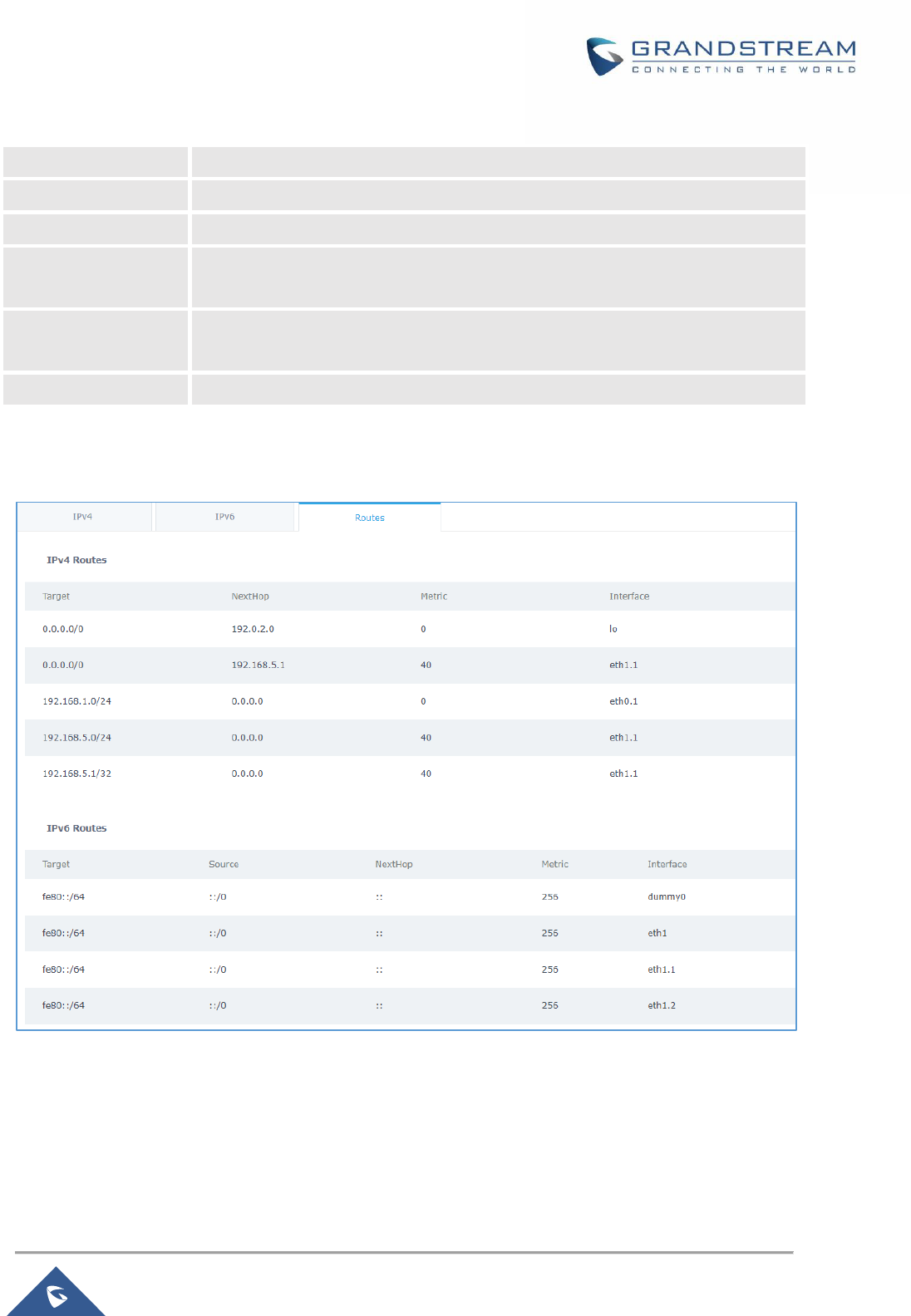
P a g e | 48
GWN7000 User Manual
Version 1.0.9.6
Table 19: IPv6 Static Routes
Name
Enter the Name of the static route to be configured.
Enable
Select whether to enable or disable this static route.
Interface
Choose the LAN network or WAN port, which will be using this static route.
Target Network/Host
Enter the Network/Host IP address on which to route the traffic to.
2001:db8:3c4d:4::/64
NextHop
Enter the Gateway’s IP address.
fec0:470:28:5b2::1/64
Metric
Set the metric value. The valid range is 0-255. Default value is 1.
To check the routing table of the router, go under the Routes tab which displays all routes learned by the
router.
Figure 18: Routes

P a g e | 49
GWN7000 User Manual
Version 1.0.9.6
Policy Routing
Feature Overview
The Policy-based Routing feature allows a network administrator to make advanced routing decisions for
traffic passing through the router. This feature allows for high granularity control over policies that dictate
what WAN port, and even VPN tunnel, traffic should use. Traffic controlled this way can be balanced
across multiple WANs or VPNs or to have complex failover designs.
Locally generated traffic can be globally routed via the policy selected under the menu “Router → WAN →
Global Settings” in order to dictate to the router either to use failover or load-balancing for locally
generated packets.
Creating/Configuring Routing Policies
The basic flow for traffic handled by policy-based routing in GWN7000 is as follows:
• Traffic matched with a specific iptables rule is marked to be used with a Policy.
• The policy contains a list of members that can be used by the policy.
• These members point to a specific interface and define a metric or weight assigned to them which
can be used for determining load balancing and failover behavior.
• The interface can be any outgoing interface (WAN or VPN) and must be assigned a metric.
• The router then handles the routing of matched traffic to the appropriate routing tables for each
member interface for that Policy.
In order to properly implement this feature, the old per-zone and per-wan routing table design has been
removed and reworked to only use the main table. In addition, the Inter-group Traffic Forwarding is being
removed in favor of automatically creating more configurable Firewall Forwarding rules.
In order to configure a new routing policy, first users need to create members under the menu Routing →
Policy Routing → Members.
Click on button to create a new member, and configure its related metric and weight:
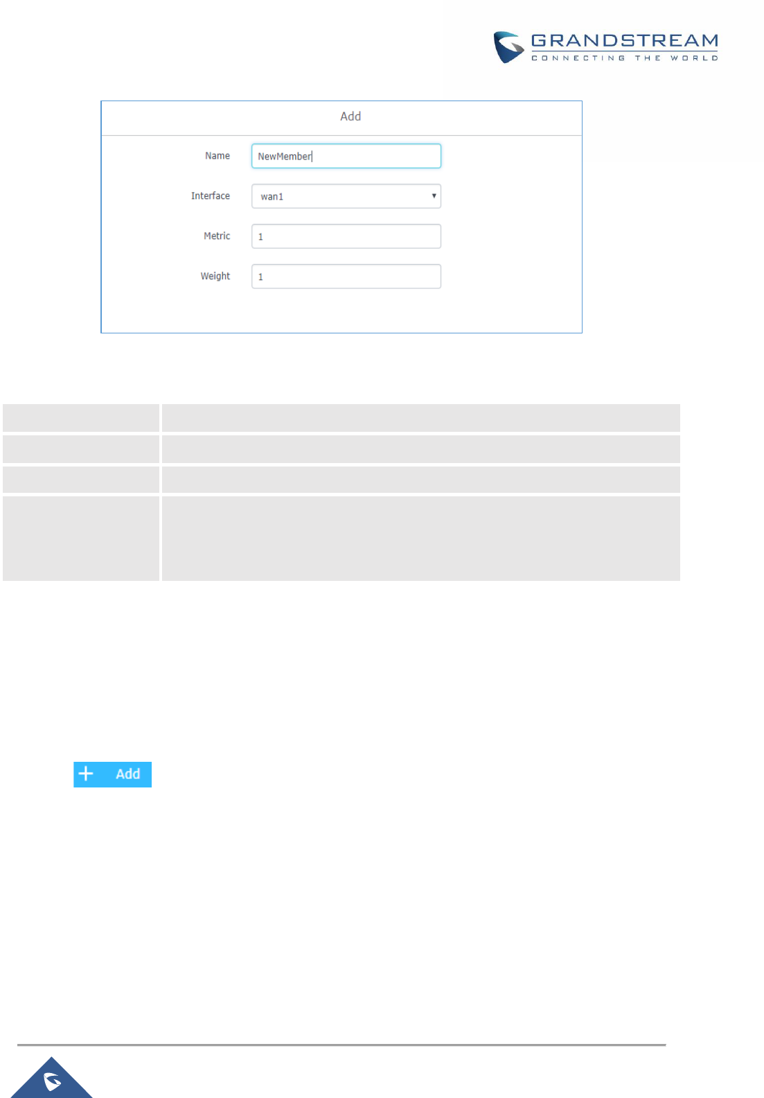
P a g e | 50
GWN7000 User Manual
Version 1.0.9.6
Figure 19: Create a New Member
Table 20: Create Policy Members
Name
Enter the Name for the member.
Interface
Select the interface to which the member points.
Metric
Enter the value of the metric related to the member (default is 1).
Weight
Enter the weight that will be attributed to the member, in case load balancing is
used, this will indicate how much traffic will be routed via this member through the
specified interface. Default value is 1.
Note: By default, GWN7000 router will generate automatically members for each created/configured WAN
interface and VPN client tunnel interface.
After this, users need to create policies which lists the members that will be used by each policy from the
menu Routing → Policy Routing → Policy.
Click on button in order to create a new routing policy then choose the members that would
be listed (included) on the policy.
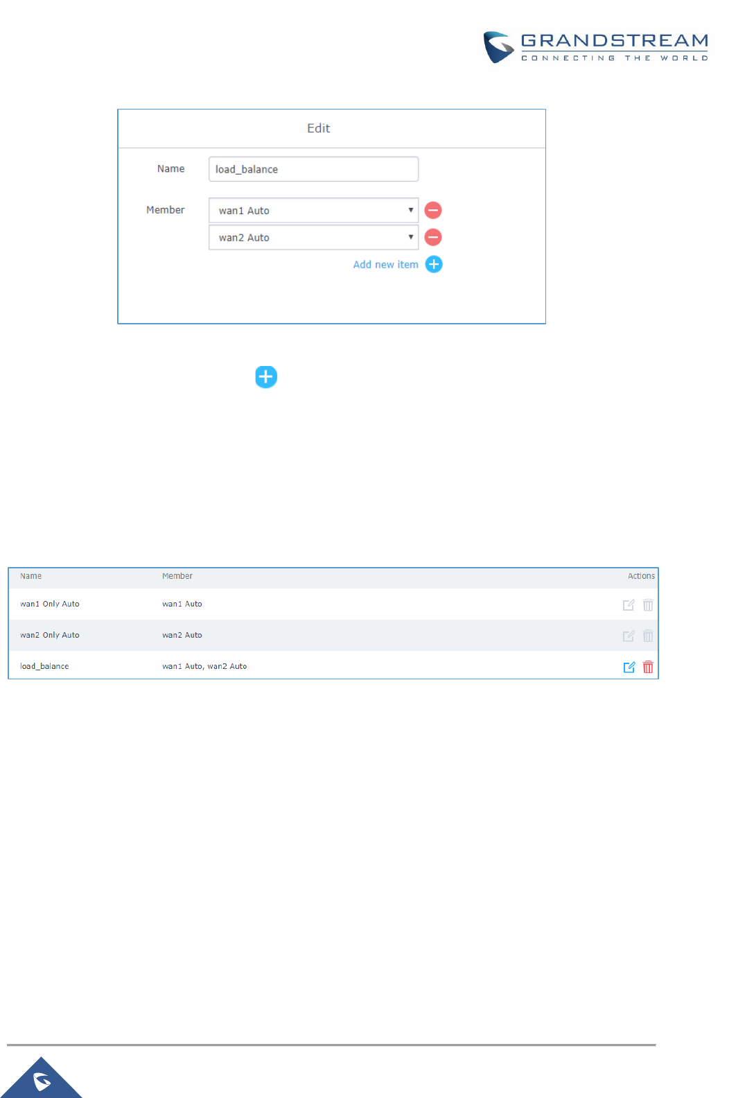
P a g e | 51
GWN7000 User Manual
Version 1.0.9.6
Figure 20: Create New Routing Policy
Give a name to the policy, then click on to add a new member to the list of members included on the
policy.
If two members have the same metric, then the policy will do load balancing through the interfaces while
taking into account the configured weight on each member to determine how much traffic can be sent
through each interface. Otherwise the member with lower metric will have priority.
Click on Save and Apply changes to save the policy and it will be displayed along the other policies on the
routers.
Note: when configuring a new LAN subnet (VLAN) or VPN client, the router will automatically generate a
routing policy in order to allow traffic from the LAN or VPN network to/via the select wan interface. Along
the automatically created routing policy, the GWN7000 router will create the corresponding firewall rule
which will allow for traffic to pass from the LAN subnet to the WAN ports while respecting the created policy,
users can check these rules under the menu “Firewall → Traffic Rules → Forward”.
Using Routing Policies
In order to illustrate how policy-based routing can be used, let’s imagine an SMB who has a GWN7000
router running their network with two WAN (WAN1 and WAN2) ports for normal data traffic and a third
WAN port (NET port used as wan) for VoIP service since this link has QoS support. The administrator
wants to send normal data traffic through WAN 1 and WAN 2 in a load balanced way and the VoIP traffic
via WAN 3 traffic.
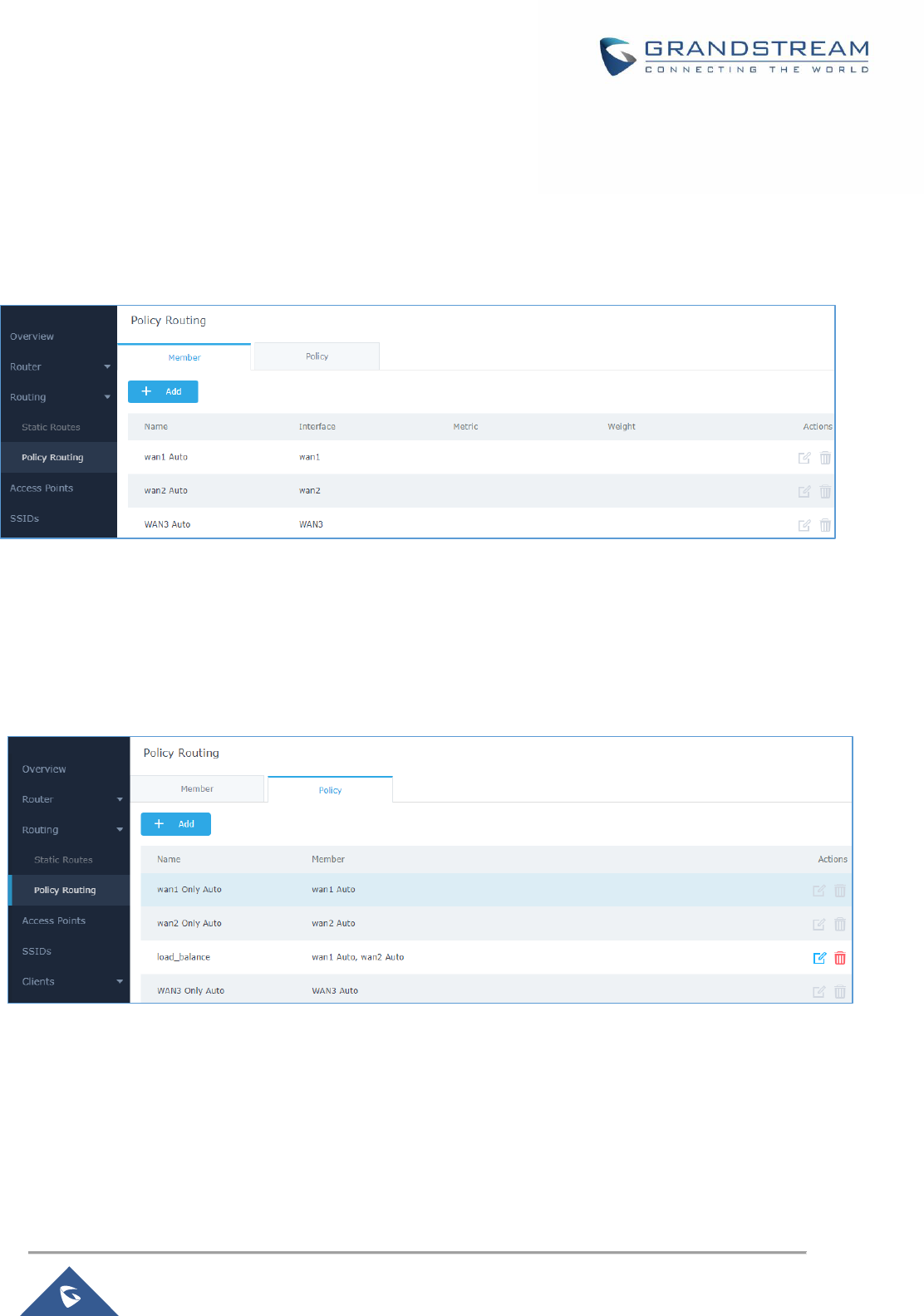
P a g e | 52
GWN7000 User Manual
Version 1.0.9.6
We consider that the administrator has already configured the three wan ports and their IP and running
which can be under the “Router → Status” page.
As explained above, the GWN7000 router will automatically generate members for the three wan ports
under “Routing → Policy Routing → Members”
Figure 21: Members list
Users can set different weights for WAN1 and WAN2 in order to set how the router will distribute the data
traffic over the two WAN ports.
Next the we will see that the router will have already created automatically the load balancing policy and
WAN3 only auto policy under Policy tab as shown on the following figure.
Figure 22: Policies List
The next step would be to assign the routing policy in order to send normal data traffic in a load-balanced
way over wan1 and wan2 and send the traffic for VoIP over wan3.
For the network group LAN data traffic, users need to navigate to Router → LAN and edit the created
network group then assign load balance routing policy and select wan1 and wan2 port as destinations.
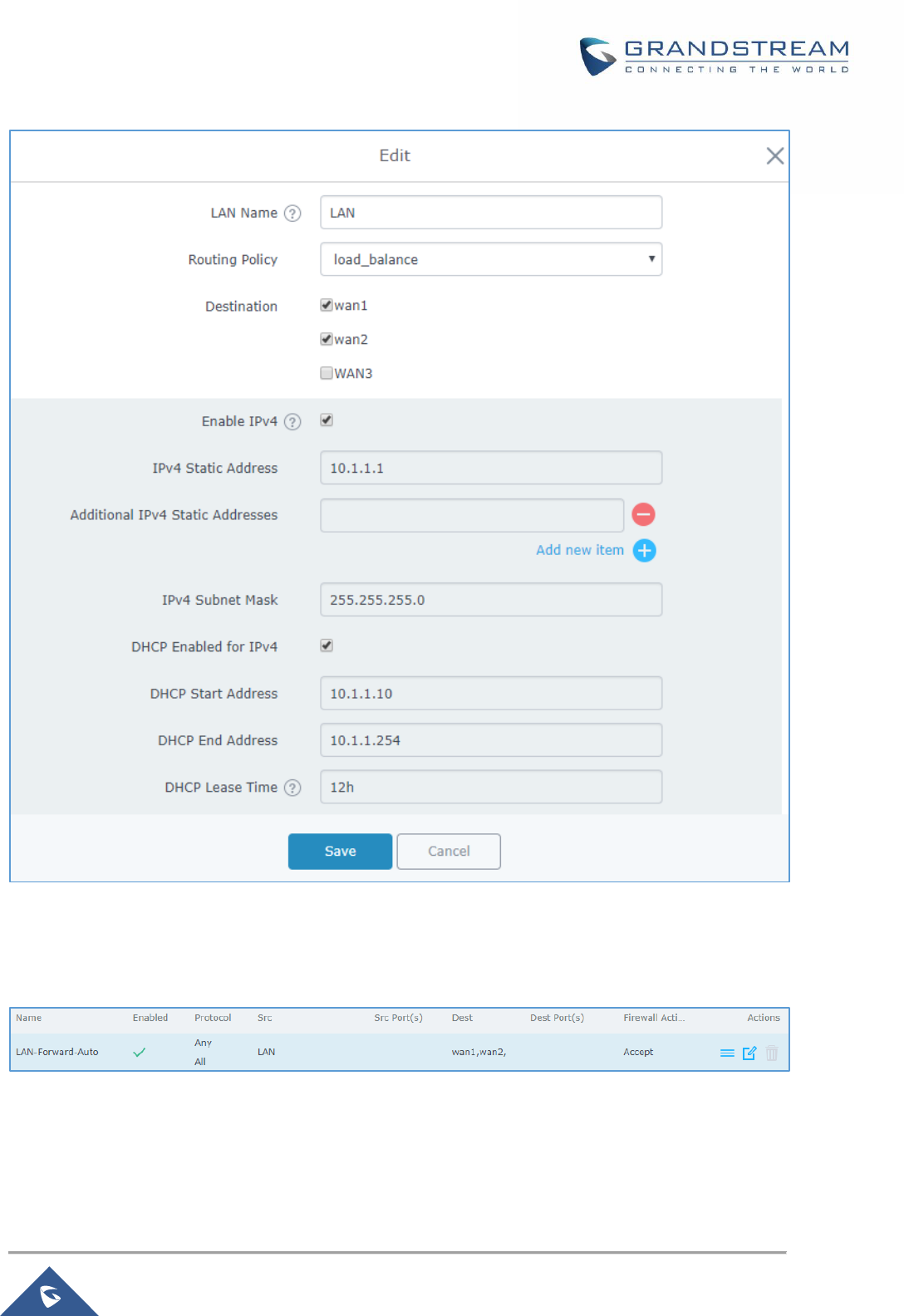
P a g e | 53
GWN7000 User Manual
Version 1.0.9.6
Figure 23: LAN Routing Policy
This will generate the firewall forward rule automatically to allow traffic to pass from LAN to WAN while
respecting the load balance policy.
For the VoIP traffic and in order to route it via the WAN3, users need to go under “Firewall → Traffic Rules
→ Forward” and add a new rule as follow.
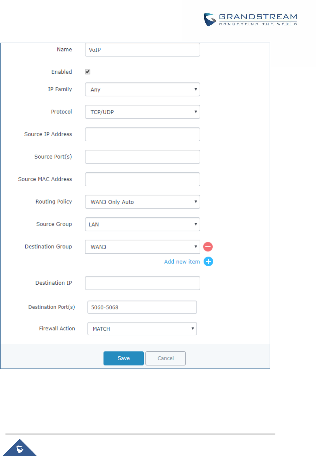
P a g e | 54
GWN7000 User Manual
Version 1.0.9.6
Figure 24: Configuring Firewall Rule using Route Policy
This way the VoIP traffic which uses the TCP or UDP ports 5060 through 5068 will be routed over WAN3.
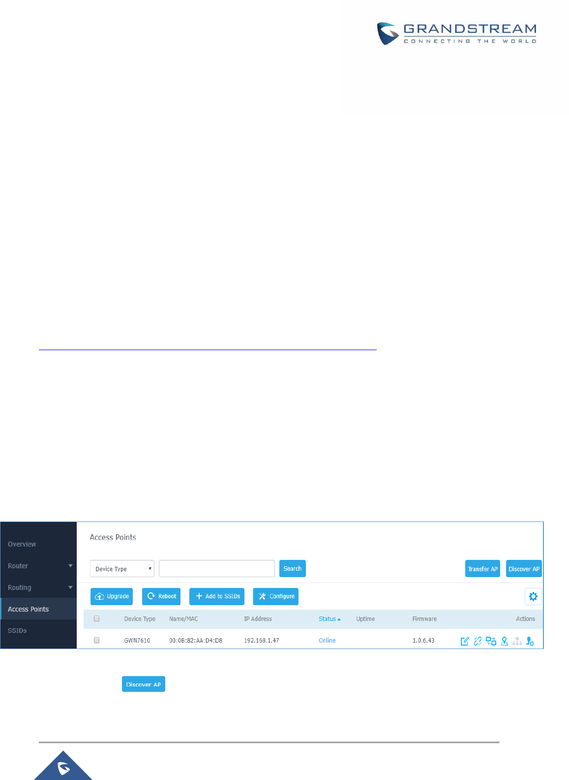
P a g e | 55
GWN7000 User Manual
Version 1.0.9.6
SETTING UP A WIRELESS NETWORK
The GWN7000 Enterprise Router provides the user with the capability to create a wireless network by
adding multiple GWN76xx series access points, with connectivity over the most common wireless
standards (802.11b/g/n) operating in both 2.4GHz and 5GHz range.
The GWN7000 integrates multiple layers of security including the IEEE 802.1x port-based authentication
protocol, Wired Equivalent Privacy (WEP), Wi-Fi Protected Access (WPA and WPA2) and firewall and VPN
tunnels.
This chapter will introduce how to discover, add the GWN76xx access points, create and manage Wi-Fi
Networks.
For more details about Grandstream GWN76xx Access points, refer to
http://www.grandstream.com/products/networking-solutions/wifi-access-points
Discover and Pair GWN76xx Access Points
The GWN76xx are powerful access points, which are fully compatible with the GWN7000 and can be
added with one click, provisioned and managed in an easy and intuitive way. Once a GWN76xx is
successfully connected and has an IP from the GWN7000 router, user can then pair it to the GWN7000
and associate it with an SSID.
To Pair a GWN76xx access point connected as LAN client to the GWN7000, follow the below steps:
1. Connect to the GWN7000 Web GUI and go to Access Points.
Figure 25: Discover AP
2. Click on to discover access points within GWN7000’s LAN Network, the following
page will appear.

P a g e | 56
GWN7000 User Manual
Version 1.0.9.6
Figure 26: Discovered Devices
3. Click on Pair under Actions, to pair the discovered Access Point with the GWN7000.
4. The paired GWN76xx will appear Online, Click on to unpair it.
Figure 27: GWN7610 online
5. Click on next to paired access point to check device configuration for its status, users
connected to it and configuration, or select multiple GWN76xx APs from the same model, and
click on to apply same configuration on selected units.
6. Click on to configure client bridge on the selected access point. For more details about the
client bridge feature, please refer to Client Bridge.
Refer to below table for Device Configuration tabs.
Table 21: Device Configuration
Status
Shows the device’s status information such as Firmware version, IP
Address, Link Speed, Uptime, and Users count via different Radio
channels.
Clients
Shows the Clients connected to the GWN76xx access point.
Configuration
• Device Name: Set GWN76xx’s name to identify it along with its
MAC address.
• Fixed IP: Used to set a static IP for the GWN76xx, if checked, the
following needs to be configured:

P a g e | 57
GWN7000 User Manual
Version 1.0.9.6
-IPv4 Address: Enter the IPv4 address to be set as static for the
device
-IPv4 Subnet Mask: Enter the Subnet Mask.
-IPv4 Gateway: Enter the Network Gateway’s IPv4 Address.
-Preferred IPv4 DNS: Enter the Primary IPv4 DNS.
-Alternate IPv4 DNS: Enter the Alternate IPv4 DNS.
• Frequency: Set the GWN76xx’s frequency, it can be either
2.4GHz, 5GHz or Dual-band.
• Enable Band Steering: When Frequency is set to Dual-Band,
check this option to enable Band Steering on the Access Point,
this will help redirecting clients to a radio band accordingly for
efficient use and to benefit from the maximum throughput
supported by the client.
• Mode: Choose the mode for the frequency band, 802.11n/g/b for
2.4Ghz and 802.11ac for 5Ghz.
• Channel Width: Choose the Channel Width, note that wide
channel will give better speed/throughput, and narrow channel
will have less interference. 20Mhz is suggested in very
high-density environment.
• 40MHz Channel Location: Configure the 40MHz channel
location when using 20MHz/40MHz in Channel Width, it can be
set it to be “Secondary Below Primary”, “Primary Below
Secondary” or “Auto”.
• Channel: Select “Auto” or a specific channel. Default is “Auto”.
Note that the proposed channels depend on Country Settings
under System Settings–>Maintenance.
• Enable Short Guard Interval: Check to activate this option to
half the guard interval (from 800ns to 400ns) ensuring that
distinct transmissions do not interfere with one another, this will
help increasing throughput.
• Active Spatial Streams: Choose active spatial stream. Available
options: “Auto”, “1 stream”, “2 streams” and “3 streams” (For
GWN7610).
• Radio Power: Set the Radio Power depending on desired cell
size to be broadcasted, three options are available: “Low”,
“Medium” or “High”. Default is “High”.
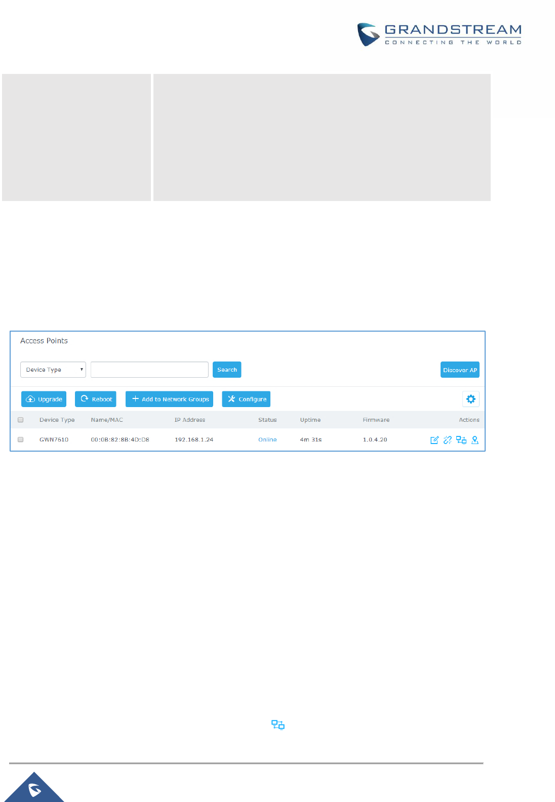
P a g e | 58
GWN7000 User Manual
Version 1.0.9.6
• Allow Legacy Device(802.11b): This feature appears when
“Mode” option is set to “802.11g” or “802.11n”, it allows legacy
devices not supporting “802.11g/n” mode to connect using the
“802.11b” mode.
• Custom Wireless Power(dBm): allows users to set a custom
wireless power for both 5GHz/2.4GHz band, the value of this field
must be between 1 and 31.
Access Point Location
GWN7000 router has an interesting feature to help users to locate different access points using blinking
LED, to do so go under the access points page then click on button as shown on the below figure and the
corresponding LED will start blinking its LEDs. This can help ease locating the Access points on a
multi-deployment site.
Figure 28: Locating Access Points
Note: If a GWN76xx is not being paired, or the pair icon is grey color, make sure that it is not being paired
with another GWN7000 Router or GWN.Cloud or GWN76xx Access Point acting as Master Controller, if
yes, it needs to be unpaired first, or reset to factory default settings to make it available for pairing; or
delete it from GWN.Cloud paired Access Points if the unit is paired to GWN.Cloud.
Client Bridge
The Client Bridge feature allows an access point to be configured as a client for bridging wired only clients
wirelessly to the network. When an access point is configured in this way, it will share the WiFi connection
to the LAN ports transparently. This is not to be confused with a mesh setup. The client will not accept
wireless clients in this mode.
Once LAN network has a Client Bridge Support enabled, the AP adopted in this LAN network can be
turned in to Bridge Client mode by click the Bridge button .
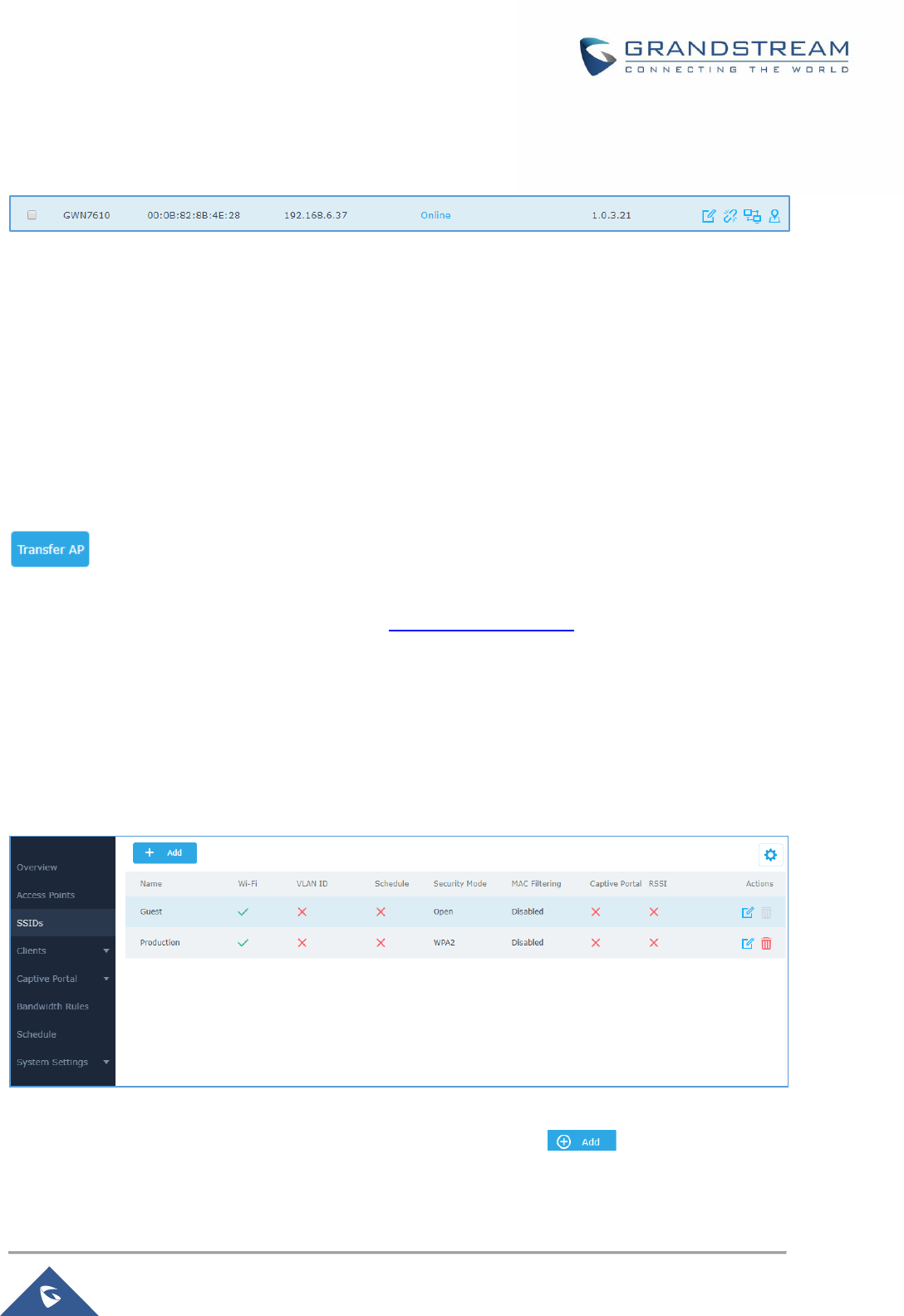
P a g e | 59
GWN7000 User Manual
Version 1.0.9.6
Please be noted that once an AP it turned into Client Bridge mode, it cannot be controlled by a Master
anymore, and a factory reset is required to turn it back into normal AP mode.
Figure 29: Client Bridge
Important Notes:
• The access point that will be operating on bridge mode, must be set with a fixed IP address before
activating the bridge mode on the access point.
• Users must enable client bridge support option under LAN or SSID WiFi settings in order to have it
fully functional. See [Client Bridge Support]
Transfer AP
Users can easily transfer the AP from local master to the Cloud based Controller account by clicking on
. When you already have Network/WIFI configurations on your cloud account, using this
feature will let you choose existing Network/SSID to adopt your local AP. Note: Local configurations will
not be transferred. For more details, please refer to GWN.Cloud User Guide.
SSIDs
When using GWN7000 as Master Access Point, users have the ability to create different SSIDs and
adding GWN76XX Slave Access Points to each SSID depending on the needs of the customer.
Log in as Master to the GWN7000 WebGUI and go to SSIDs.
Figure 30: SSID
The GWN7000 can support the management of up to 16 SSIDs, click on to add a new SSID.
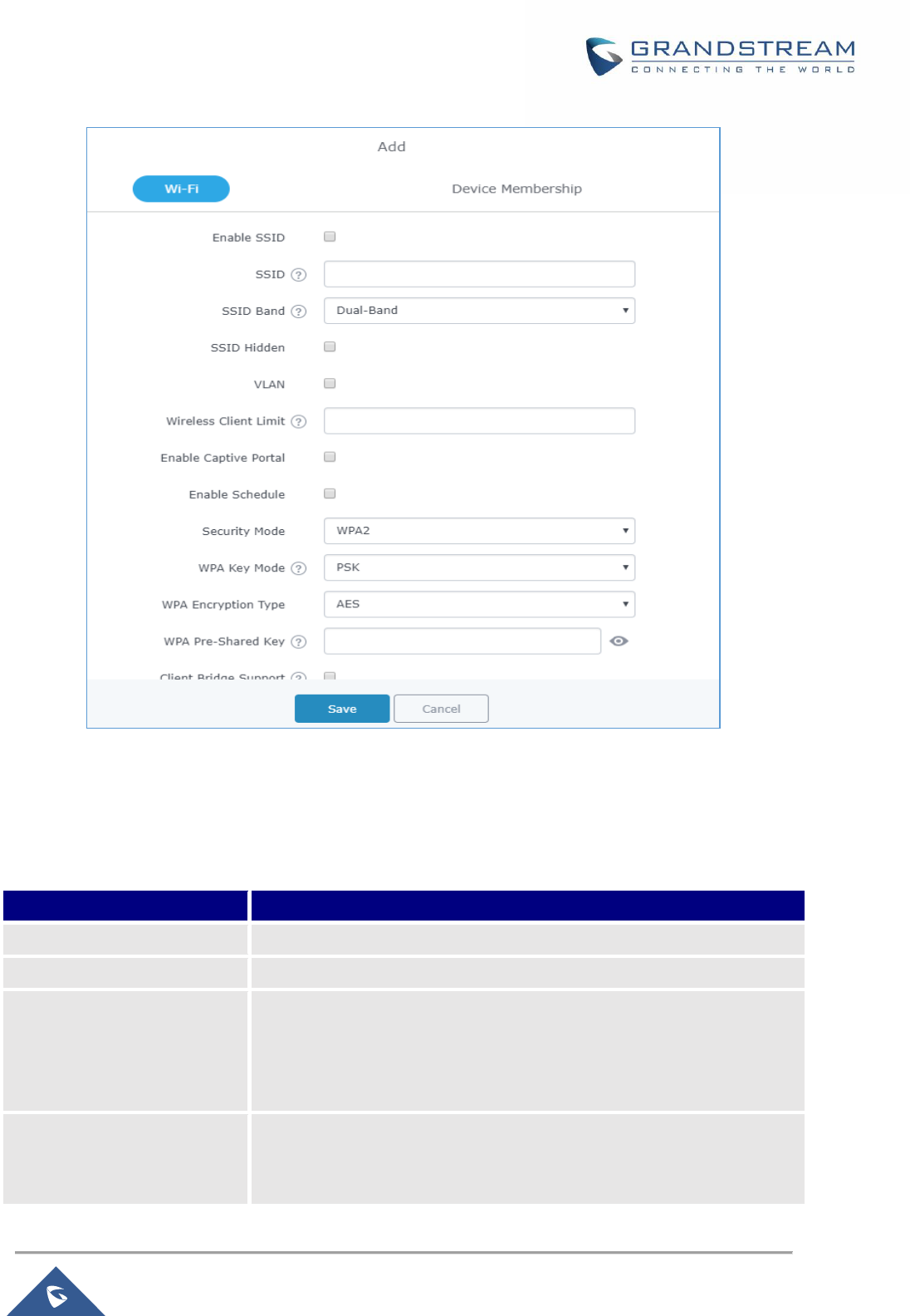
P a g e | 60
GWN7000 User Manual
Version 1.0.9.6
Figure 31: Add a new SSID
When editing or adding a new SSID, users will have two tabs to configure:
• Wi-Fi: Please refer to the below table for Wi-Fi tab options
Table 22: Wi-Fi
Field
Description
Enable SSID
Check to enable Wi-Fi for the SSID.
SSID
Set or modify the SSID name.
SSID Band
Select the Wi-Fi band the GWN will use, three options are available:
• Dual-Band
• 2.4GHz
• 5Ghz
SSID Hidden
Select to hide SSID. SSID will not be visible when scanning for Wi-Fi, to
connect a device to hidden SSID, users need to specify SSID name and
authentication password manually.

P a g e | 61
GWN7000 User Manual
Version 1.0.9.6
VLAN
Enter the VLAN ID corresponding to the SSID.
Wireless Client Limit
Configure the limit for wireless client. If there’s an SSID per-radio on a
SSID, each SSID will have the same limit. So, setting a limit of 50 will limit
each SSID to 50 users independently. If set to 0 the limit is disabled.
Enable Captive Portal
Click on the checkbox to enable the captive portal feature.
Captive Portal Policy
Select the captive portal policy already created on the “CAPTIVE
PORTAL” web page to be used in the created SSID.
Enable Schedule
Check the box and choose a schedule to apply for the selected SSID.
Security Mode
Set the security mode for encryption, 5 options are available:
• WEP 64-bit: Using a static WEP key. The characters can only be
0-9 or A-F with a length of 10, or printable ASCII characters with a
length of 5.
• WEP 128-bit: Using a static WEP key. The characters can only
be 0-9 or A-F with a length of 26, or printable ASCII characters
with a length of 13.
• WPA/WPA2: Using “PSK” or “802.1x” as WPA Key Mode, with
“AES” or “AES/TKIP” Encryption Type.
• WPA2: Using “PSK” or “802.1x” as WPA Key Mode, with “AES” or
“AES/TKIP” Encryption Type. Recommended configuration for
authentication.
• Open: No password is required. Users will be connected without
authentication. Not recommended for security reasons.
WEP Key
Enter the password key for WEP protection mode.
WPA Key Mode
Two modes are available:
• PSK: Use a pre-shared key to authenticate to the Wi-Fi.
• 802.1X: Use a RADIUS server to authenticate to the Wi-Fi.
WPA Encryption Type
Two modes are available:
• AES: This method changes dynamically the encryption keys
making them nearly impossible to circumvent.
• AES/TKIP: use both Temporal Key Integrity Protocol and
Advanced Encryption Standard for encryption, this provides the
most reliable security.
WPA Pre – Shared Key
Set the access key for the clients, and the input range should be: 8-63
ASCII characters or 8-64 hex characters.

P a g e | 62
GWN7000 User Manual
Version 1.0.9.6
Client Bridge Support
Configures the client bridge support to allow the access point to be
configured as a client for bridging wired only clients wirelessly to the
network. When an access point is configured in this way, it will share the
WiFi connection to the LAN ports transparently. Once a SSID has a Client
Bridge Support enabled, the AP adopted in this SSID can be turned in to
Bridge Client mode by click the Bridge button.
RADIUS Sever Address
Configures RADIUS authentication server address.
RADIUS Server Port
Configures RADIUS Server Listening port.
Default is: 1812.
RADIUS Server Secret
Enter the secret password for client authentication with RADIUS server.
RADIUS Accounting Server
Configures the address for the RADIUS accounting server.
RADIUS Accounting Server
Port
Configures RADIUS accounting server listening port (defaults to 1813).
RADIUS Accounting Server
Secret
Enter the secret password for client authentication with RADIUS
accounting server.
Client Time Policy
Select a time policy to be applied to all clients connected to this SSID.
Use MAC Filtering
Choose Blacklist/Whitelist to specify MAC addresses to be
excluded/included from connecting to the zone’s Wi-Fi.
Default is Disabled.
Enable Dynamic VLAN (beta)
When enabled, clients will be assigned IP address from corresponding
VLAN configured on the RADIUS user profile.
This field is available only when “WPA Key Mode” is set to “802.1x”.
Client Isolation
Client isolation feature blocks any TCP/IP connection between connected
clients to GWN76XX’s Wi-Fi access point.
Client isolation can be helpful to increase security for Guest
networks/Public Wi-Fi.
Three modes are available:
• Internet Mode: Wireless clients will be allowed to access only the
internet services and they cannot access any of the management
services, either on the router nor the access points GWN76XX.
• Gateway MAC Mode: Wireless clients can only communicate with
the gateway, the communication between clients is blocked and
they cannot access any of the management services on the
GWN76XX access points.

P a g e | 63
GWN7000 User Manual
Version 1.0.9.6
• Radio Mode: Wireless clients can access to the internet
services, GWN7xxx router and the access points GWN76XX but
they cannot communicate with each other.
Client Isolation
Client isolation feature blocks any TCP/IP connection between connected
clients to GWN76XX’s Wi-Fi access point.
Client isolation can be helpful to increase security for Guest
networks/Public Wi-Fi.
Three modes are available:
• Internet Mode: Wireless clients will be allowed to access only
the internet services and they cannot access any of the
management services, either on the router nor the access points
GWN76XX.
• Gateway MAC Mode: Wireless clients can only communicate
with the gateway, the communication between clients is blocked
and they cannot access any of the management services on the
GWN76XX access points.
• Radio Mode: Wireless clients can access to the internet
services, GWN7xxx router and the access points GWN76XX but
they cannot communicate with each other.
Gateway MAC Address
This field is required when using Client Isolation set to Gateway MAC,
so users will not lose access to the Network (usually Internet).
Type in the default LAN Gateway’s MAC address (router’s MAC address
for instance) in hexadecimal separated by “:”. Example:
00:0B:82:8B:4D:D8
Enable Minimum RSSI
Check to enable RSSI function, this will lead the AP to disconnect users
below the configured threshold in Minimum RSSI (dBm).
Minimum RSSI (dBm)
Enter the minimum RSSI value in dBm. If the signal value is lower than
the configured minimum value, the client will be disconnected.
The input range is from “-94” or “-1”.
Beacon Interval
Configures interval between beacon transmissions/broadcasts.
The Beacon signals help to keep the network synchronized and provide
main information about the network such as SSID, Timestamp…
• Using High Beacon Interval: AP will be sending beacon
broadcast less frequently.

P a g e | 64
GWN7000 User Manual
Version 1.0.9.6
This will help to get better throughput, thus better
speed/performance. It also helps to save WiFi clients energy
consumption.
• Using Low Beacon Interval: AP will be sending beacon
broadcast more frequently. This can help in environments with
weak signal areas; sending more frequently beacons will
increase chances to be received by WiFi clients with weak signal.
Notes:
1. When AP enables several SSIDs with different interval values, the
max value will take effect.
2. When AP enables less than 3 SSIDs, the interval value which will
be effective are the values from 40 to 500.
3. When AP enables more than 2 but less than 9 SSIDs, the interval
value which will be effective are the values from 100 to 500.
4. When AP enables more than 8 SSIDs, the interval value which will
be effective are the values from 200 to 500.
5. Mesh feature will take up a share when it is enabled.
Default value is 100ms. Valid range: 40 – 500 ms.
DTIM Period
Configures the frequency of DTIM (Delivery Traffic Indication Message)
transmission per each beacon broadcast. Clients will check the AP for
buffered data at every configured DTIM Period. You may set a high value
for power saving consideration.
Default value is 1, meaning that AP will have DTIM broadcast every
beacon. If set to 10, AP will have DTIM broadcast every 10 beacons.
Valid range: 1 – 10.
Multicast to Unicast
Once selected, AP will convert multicast streams into unicast streams
over the wireless link. Which helps to enhance the quality and reliability of
video/audio stream and preserve the bandwidth available to the
non-video/audio clients.
Enable Voice Enterprise
Check to enable/disable Voice Enterprise. The roaming time will be
reduced once enable voice enterprise.
• The 802.11k standard helps clients to speed up the search for
nearby APs that are available as roaming targets by creating an
optimized list of channels.

P a g e | 65
GWN7000 User Manual
Version 1.0.9.6
When the signal strength of the current AP weakens, your device
will scan for target APs from this list.
• When your client device roams from one AP to another on the
same network, 802.11r uses a feature called Fast Basic Service
Set Transition (FT) to authenticate more quickly. FT works with
both pre-shared key (PSK) and 802.1X authentication methods.
• 802.11v allows client devices to exchange information about the
network topology, including information about the RF
environment, making each client network aware, facilitating
overall improvement of the wireless network.
Note: 11R is required for enterprise audio feature, 11V and 11K are
optional. This field is available only when “Security Mode” is set to
“WPA/WPA2” or “WPA2”.
Enable 11R
Check to enable 802.11r
Enable 11K
Check to enable 802.11k
Enable 11V
Check to enable 802.11v
ARP Proxy
This option will enable GWN AP to answer the ARP requests from its LAN
for its connected WiFi clients. This is mainly to reduce the airtime
consumed by ARP Packets
• Device Membership: Used to add or remove paired access points to the SSID.
Figure 32: Device Membership

P a g e | 66
GWN7000 User Manual
Version 1.0.9.6
Click on to add the GWN7600/GWN7600LR to the SSID or click on to remove it.
Mesh Network
In Mesh Network, wireless connection is established between multiple Aps, which is used to passthrough
data traffic rather than client association. Each AP will evaluate the performance of wireless channel based
on several factors and choose one or multiple appropriate APs to setup connection.
In a mesh network, access points are categorized to two types:
• CAP (Central Access Point): this is an access point that has an uplink connection to the wired
network.
• RE (Range Extender): This is an access point that participate on the mesh network topology and has
a wireless uplink connection to the central network.
In order to deploy mesh access points (RE), users/installers can follow below steps:
1. Make sure to have the master and CAP access points already deployed (sometimes the CAP
access points can be the master controller of the network).
2. Next, we need to pair the RE access points to the master. This can be done in two ways:
A. Connect all REs to the same wired LAN as the master then perform the normal process of
discovery/pairing process, and after successfully pairing the APs they can be deployed on the
field.
B. REs can also be discovered wirelessly when powered via PSU or PoE Injector, and admin can
configure them after discovery. This requires that the REs must be within the range of the
Master or CAP Slave’s signals coverage.
Note: If there are other GWN APs broadcasting in the same field with different subnet, RE may
be wirelessly connected to those networks and cannot be discovered and paired by your
Master. Therefore, it is recommended to use the first method of wired pairing and then deploy
those REs.
3. After that all slave access points have been deployed and paired to the master, you can directly
manage them to operate the mesh network. Mesh service configuration is the same as transitional
GWN WLAN.
4. Log into the master page, and under Access Points page you can see the information, for
example the AP in the “Online Wireless” state is the RE (Range Extender) with a wireless uplink
to the CAP. The APs showing “Online” state are either a wired master or CAP.
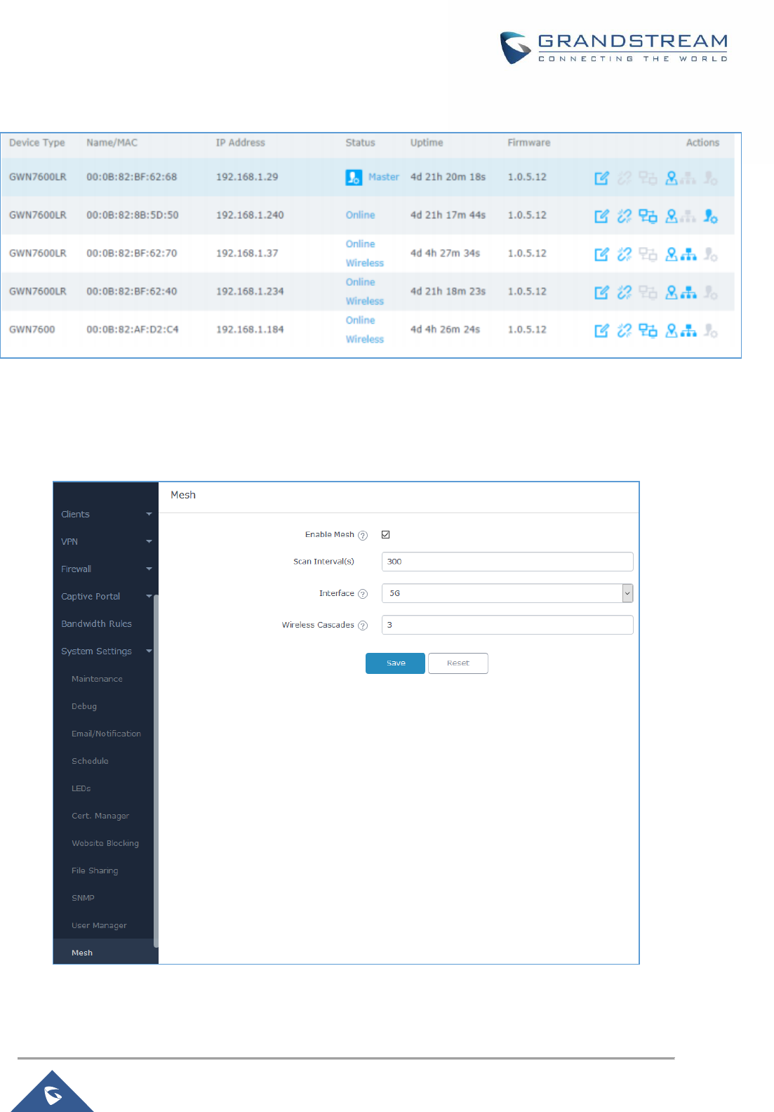
P a g e | 67
GWN7000 User Manual
Version 1.0.9.6
Figure 33: Access Points Status
For Global mesh network settings, navigate to the menu “System Settings → Mesh” for setting up the
following parameters described below:
Figure 34: Mesh Settings
P a g e | 68
GWN7000 User Manual
Version 1.0.9.6
The following table describes the Mesh configuration settings.
Table 23: Wi-Fi
For more detailed information about GWN Mesh network feature, you may refer to the following technical
document: Mesh Network Guide.
Upgrading Access Points
Single Access Point upgrade
If you want to upgrade a single access point, users need to select the AP then simply click on the
button to launch the upgrade process, the AP will use the same parameters configured for
the router under the menu System Settings → Maintenance → Upgrade.
Otherwise, is users want to upgrade many devices at the same time, make sure to select all desired
access points, then press the button, the router will give the option to choose between
upgrading all access points at once which will result in all the devices downloading the firmware at the
same time and consuming bandwidth or making sequential upgrade which is the recommended option
described below.
Sequential Upgrade
If you choose multiple slave devices to upgrade their firmware, two options are available: “All-at-Once” and
“Sequential”. “All-at-Once” will use the default method, all checked slaves will upgrade their firmware at the
same time, while using “Sequential” upgrade method, the slaves will upgrade their firmware one by one in
order to:
• Avoid entire Wi-Fi service interruption by full system firmware upgrade.
Filed
Description
Enable Mesh
When checked the Mesh feature will be activated.
Scan Interval
Interval in seconds to scan for available Mesh neighbors. Must be less
than or equal to 300 seconds.
Interface
Select either 2.4GHz or 5GHz band.
Wireless cascades
Define how many AP can be cascaded wirelessly with the AP. The
minimum value is 1 and maximum value is 3.
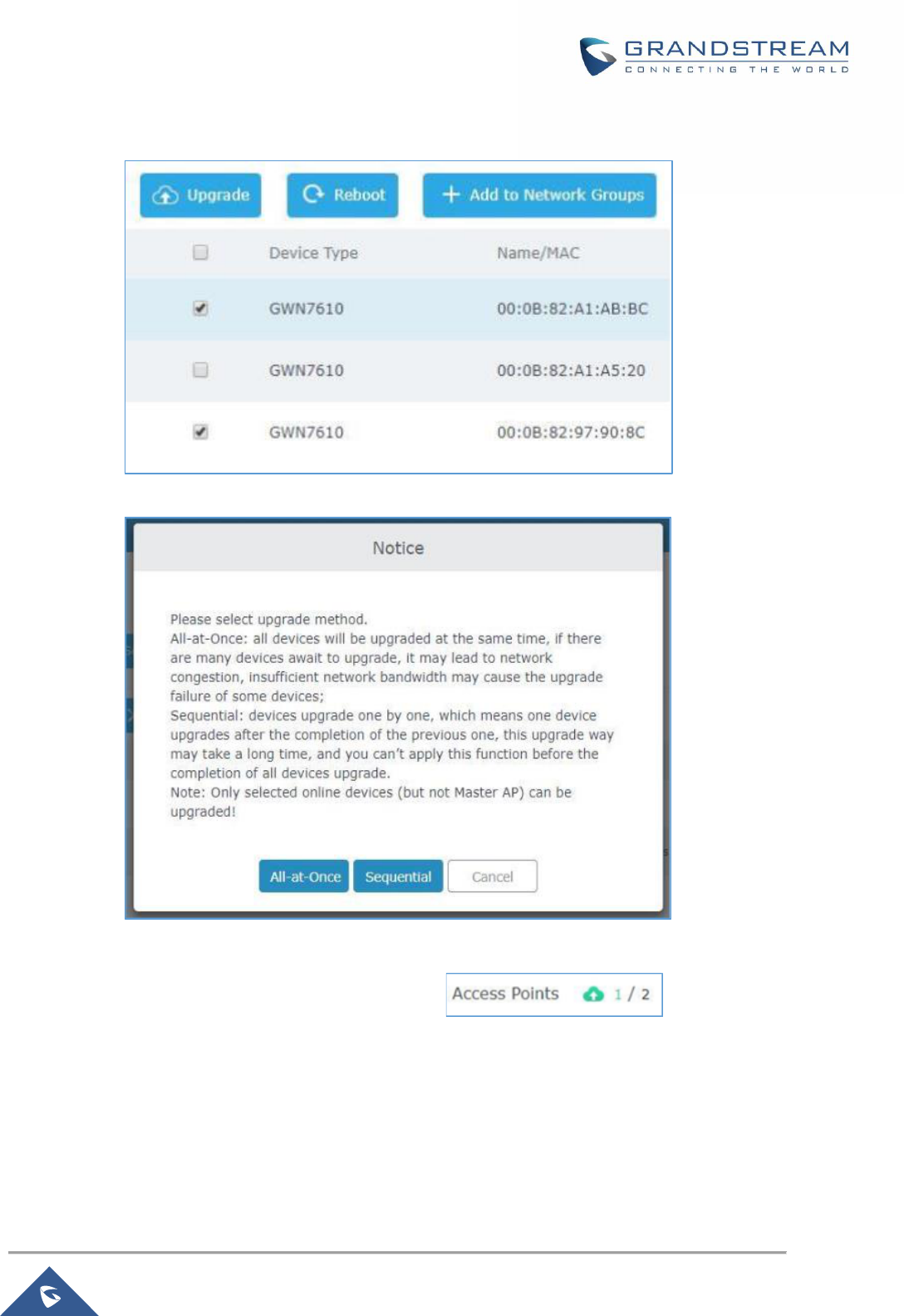
P a g e | 69
GWN7000 User Manual
Version 1.0.9.6
• Reduce network bandwidth consumption caused by firmware downloading.
Figure 35: Sequential Upgrade - Choosing Multiple Devices
Figure 36: All-at-Once and Sequential Upgrade
Once you choose sequential upgrade, the following icon will update you
about the number of upgraded slaves out of the selected slaves.
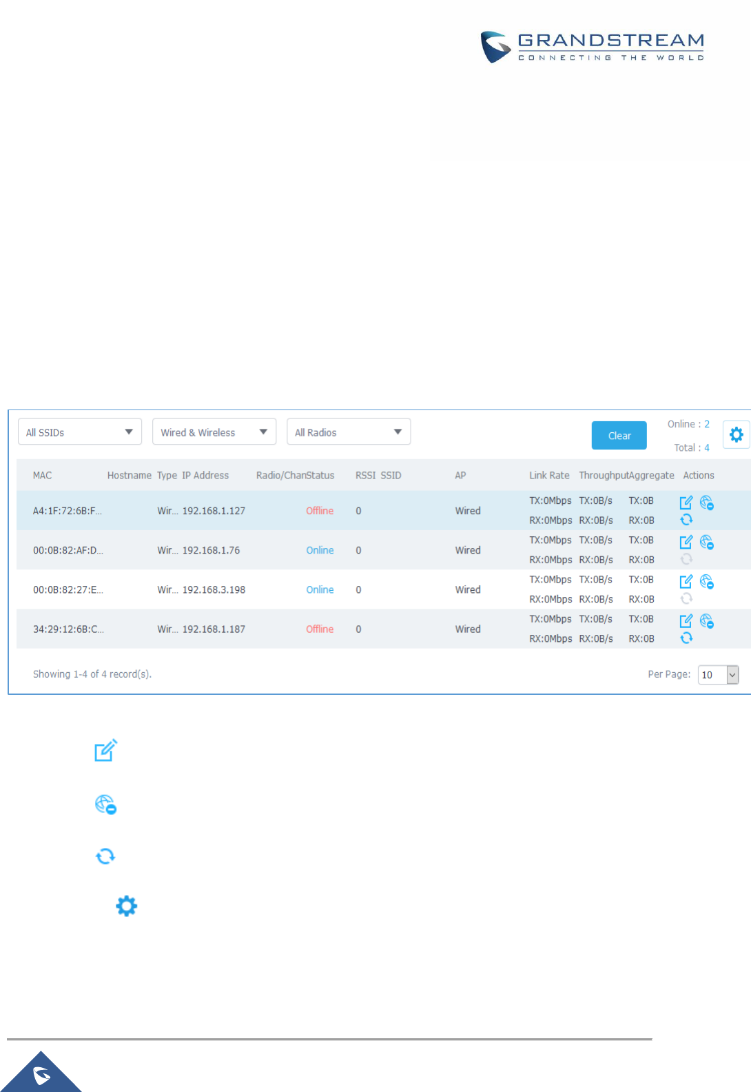
P a g e | 70
GWN7000 User Manual
Version 1.0.9.6
CLIENTS CONFIGURATION
Clients
Connected clients to different LAN subnets can be shown and managed from a single interface.
Clients list can be accessed from GWN7000’s Web GUI→Clients to perform different actions to wired and
wireless clients.
GWN7000 Enterprise Router with its DHCP server enabled on LAN ports level, will assign automatically an
IP address to the devices connected to its LAN ports like a computer or GWN76xx access points and to
wireless clients connected to paired GWN76xx access points.
Figure 37: Clients
• Click on under Actions to check client’s status and modify basic settings such Device’s Name.
• Click on to block a client’s MAC address from connecting to the zone’s SSID.
• Click on to release Wi-Fi offline client IP lease.
Users can press button to customize items to display on the page. Following items are supported:
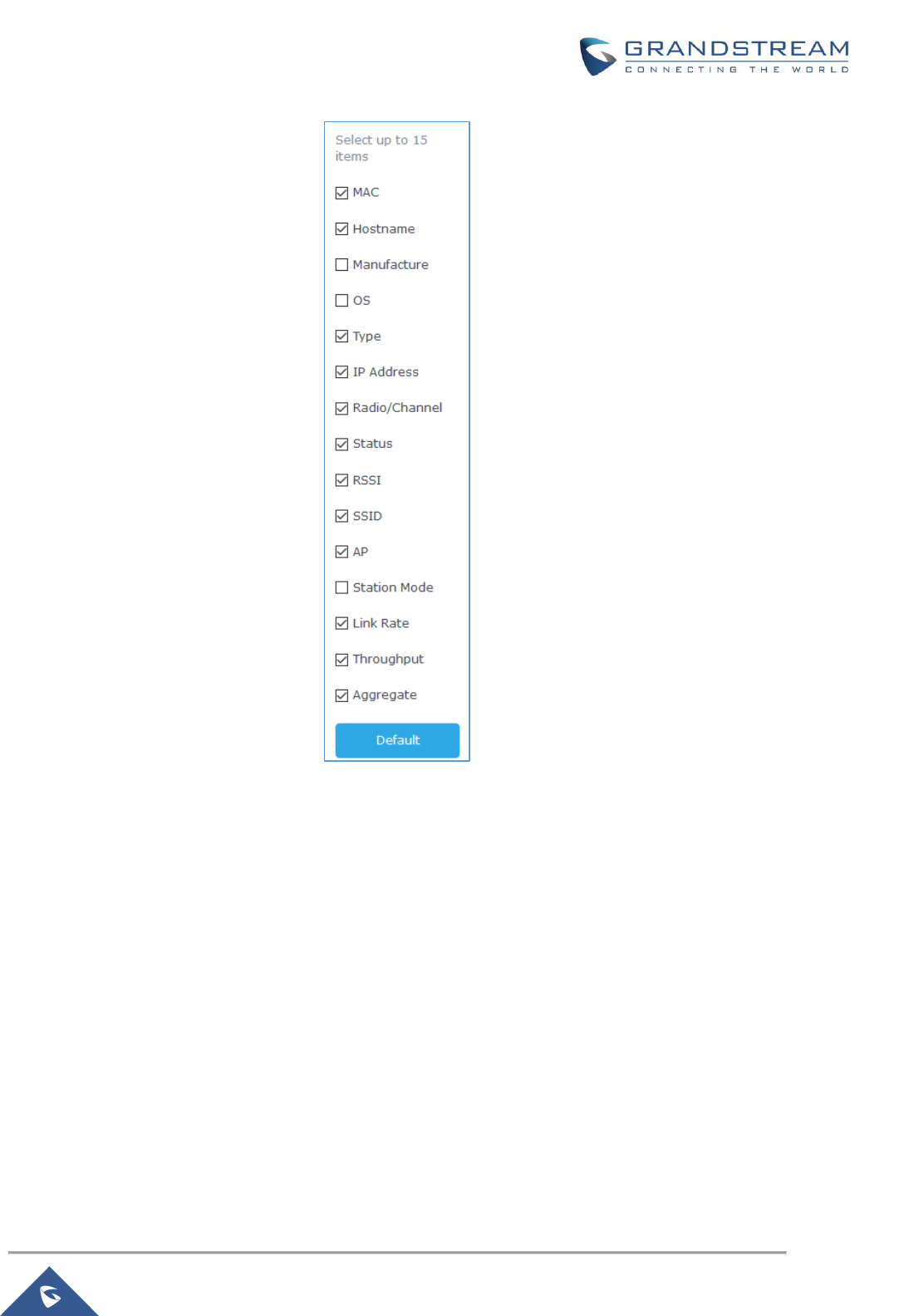
P a g e | 71
GWN7000 User Manual
Version 1.0.9.6
Figure 38: Clients - Select Items
Note: One of the enhancements on this section starting from 1.0.9.4 is the Link Rate that shows the client
negotiated speed.
Status
Used to check user’s basic information such as MAC address, IP address, which Network group does it
belong to, and to which access point if it is a wireless client, as well as Throughput and Aggregate usage.
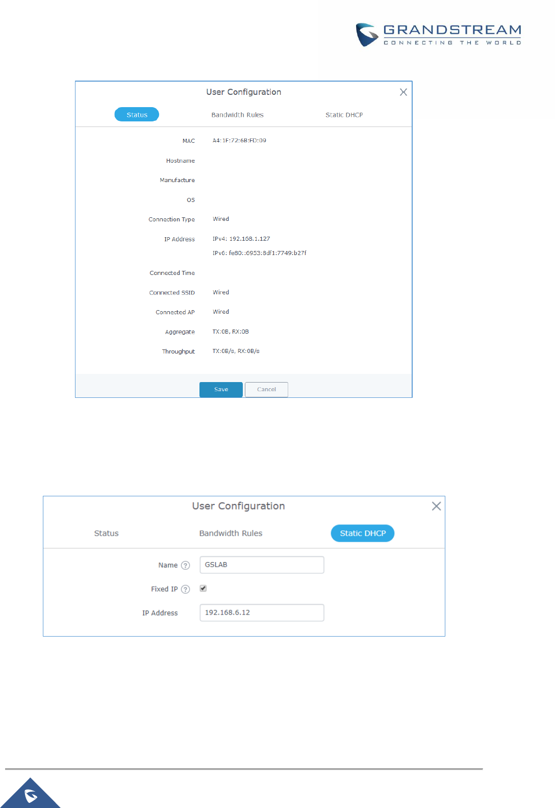
P a g e | 72
GWN7000 User Manual
Version 1.0.9.6
Figure 39: Client's Status
Edit IP and Name
Configuration tab allowing to set a name for a client and set a static IP.
Figure 40: Client's Configuration
Bandwidth Rules
As mentioned on the BANDWIDTH RULES section, users can set bandwidth rules for upstream and
downstream links per SSID, or per Client. For Clients users can set bandwidth rules by navigating to the
menu Client→Edit→Bandwidth Rules then click add new item.
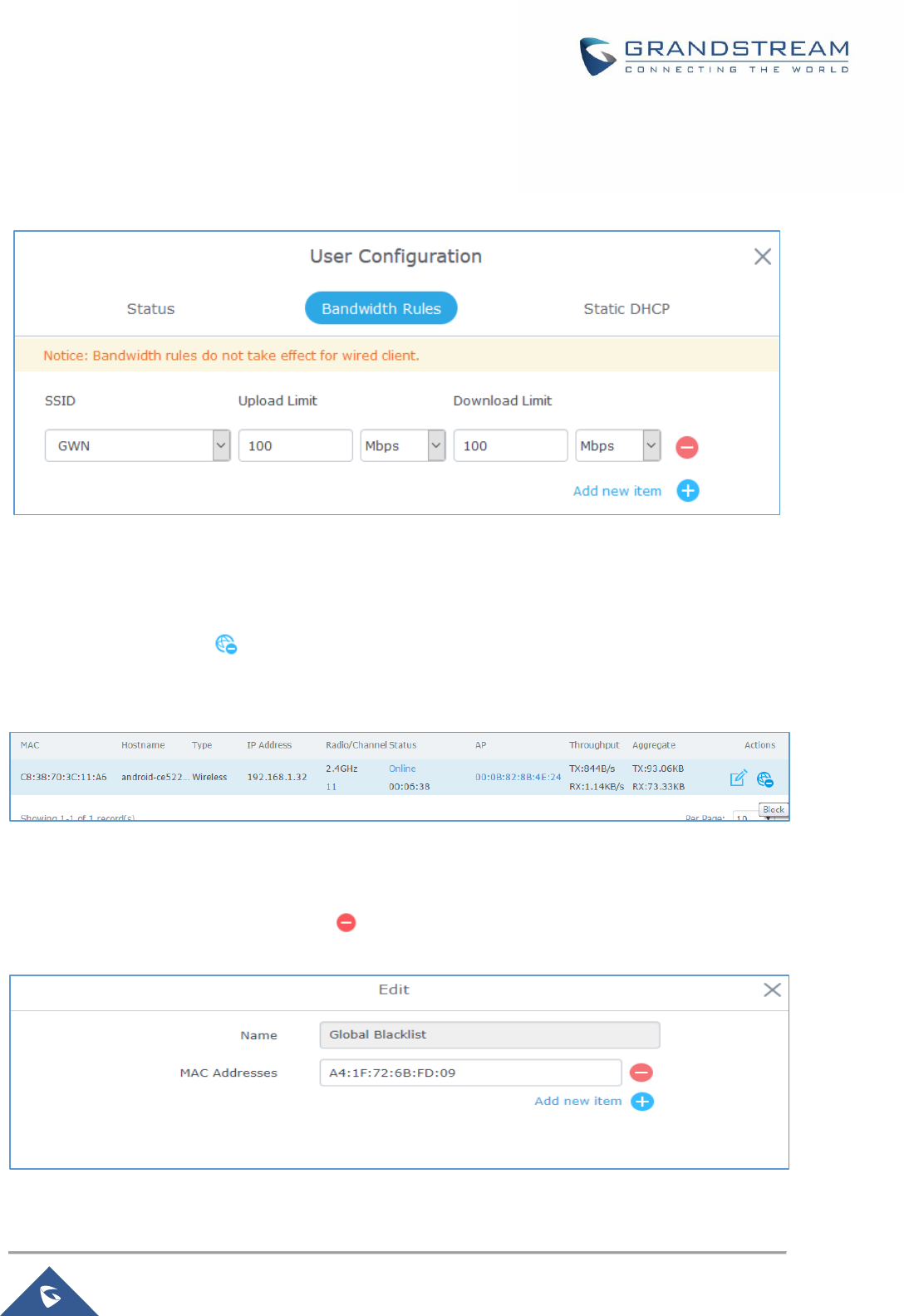
P a g e | 73
GWN7000 User Manual
Version 1.0.9.6
Note: Bandwidth rules apply for wireless clients ONLY.
The following figure shows the settings:
Figure 41: Client Bandwidth Rules
Block a Client
To block a client, click on under actions, this will add automatically the blocked client to Banned
Client MAC list under Router→Port→Global Settings.
Figure 42: Block a Client
To unban a client, go to Router→Clients→Client Access. The banned client will be to “Global Blacklist”;
you will need to click on “Edit” then Click on to remove it from the banned list.
Figure 43: Unban Client
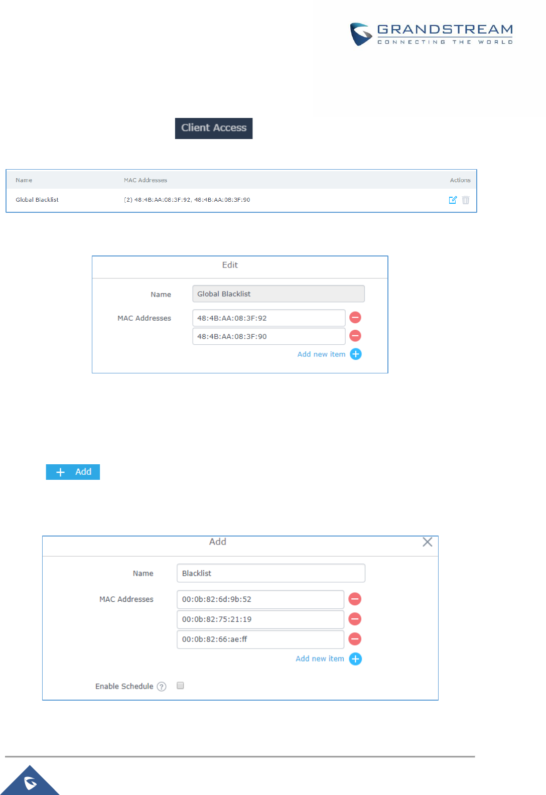
P a g e | 74
GWN7000 User Manual
Version 1.0.9.6
Clients Access
From this menu, users can manage in global and way the blacklist of clients that will be blocked from
accessing the WiFi network, click on to add or remove MAC addresses of client from
global blacklist.
Figure 44: Global Blacklist
Figure 45: Managing the Global Blacklist
A second option is to add custom access lists that will be used as matching mechanism for MAC address
filtering option under SSIDs to allow (whitelist) or disallow (blacklist) clients access to the WiFi network.
Click on in order to create new access list, then fill it with all MAC addresses to be matched
and assign to it a schedule. Once this is done, this access list can be used under SSID WiFi settings to
filter clients either using whitelist or blacklist mode.
Figure 46: Adding a MAC Access List
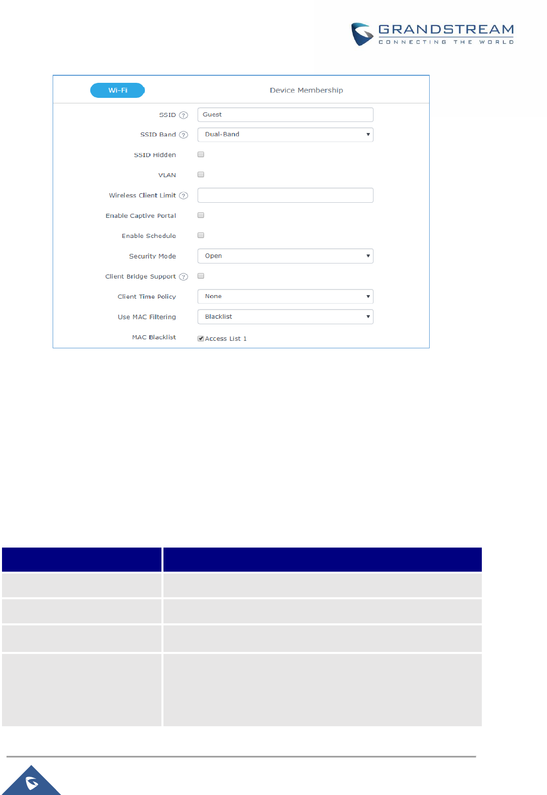
P a g e | 75
GWN7000 User Manual
Version 1.0.9.6
Figure 47: Blacklist Access List
Time Policy
The timed client disconnect feature allows the system administrator to set a fixed time for which clients
should be allowed to connect to the access point, after which the client will no longer be allowed to connect
for a user configurable cool-down period. The configuration is based on a policy where the administrator
can set the amount of time for which clients are allowed to connect to the WiFi and reconnect type and
value after which they will be allowed to connect back after they have been disconnected.
In order to create a new policy, go under Clients→Time Policy and add new one, then the following
parameters:
Table 24: Time Policy Parameters
Option
Description
Name
Enter the name of the policy
Enabled
Check the box to enable the policy
Limit Client Connection Time
Sets amount of time a client may be connected.
Client Reconnect Timeout Type
Select the method with which we will reset a client’s connection timer,
so they may reconnect again. Options are:
• Reset Daily.
• Reset Weekly.
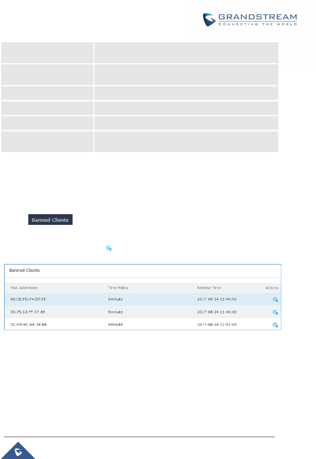
P a g e | 76
GWN7000 User Manual
Version 1.0.9.6
• Reset Hourly.
• Timed Reset.
Client Reconnect Timeout
If ‘Timed Reset’ is selected, this is the period for which the client will
have to wait before reconnecting.
Hour of the Day
If Reset Daily is selected, this is the hour the reset will be applied.
Day of the Week
If Reset Weekly is selected, this is the day the reset will be applied.
Hour of the Week
If Reset Weekly is selected, this is the hour the reset will be applied.
Reset Hour
If Reset Weekly or Reset Daily is select, this is the hour and day the
reset will be applied.
Note: Time tracking shall be accounted for on a per-policy basis, such that a client connected to any SSID
assigned the time tracking policy will accrue a common counter, regardless of which SSID they are
connected to (as long as those SSIDs all share the same time tracking policy).
Banned Clients
Click on to view the list of the clients that have been banned after time disconnect
feature has taken effect, these clients will not be allowed to connect back until timeout reset or you can
unblock a client by clicking on the icon .
Figure 48: Ban/Unban Client

P a g e | 77
GWN7000 User Manual
Version 1.0.9.6
VPN (VIRTUAL PRIVATE NETWORK)
Overview
VPN allows the GWN7000 to be connected to a remote VPN server using PPTP, IPSec, L2TP/IPSec and
OpenVPN® protocols, or configure an OpenVPN® server and generate certificates and keys for clients,
VPN page can be accessed from the GWN7000 Web GUI→VPN.
OpenVPN® Server Configuration
To use the GWN7000 as an OpenVPN® server, you will need to start creating user account, OpenVPN®
server certificates and client certificates. Before generating server/client certificates, it is requested to
generate first the Certificate Authority (CA), which will help to issue server/clients certificates.
GWN7000 certificates can be managed from WebGUI→System Settings→Cert. Manager.
Generate Self-Issued Certificate Authority (CA)
A certificate authority (CA) is a trusted entity that issues electronic documents that verify a digital entity's
identity on the Internet. The electronic documents (a.k.a. digital certificates) are an essential part of secure
communication and play an important part in the public key infrastructure (PKI).
To create a Certification Authority (CA), follow below steps:
1. Navigate to “System Settings→Cert. Manager→CAs” on the GWN7000 web GUI.
2. Click on button. A popup window will appear.
3. Enter the CA values including CN, Key Length, and Digest algorithm… depending on your needs.
Refer to below figure showing an example of configuration and below table showing all available
options with their respective description.
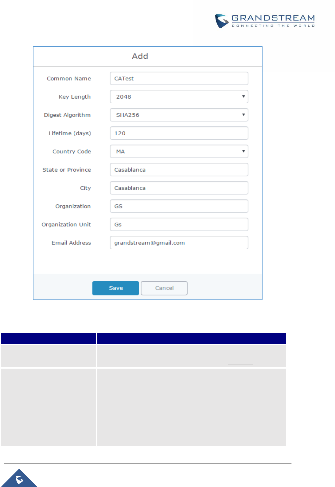
P a g e | 78
GWN7000 User Manual
Version 1.0.9.6
Figure 49: Create CA Certificate
Table 25: CA Certificate
Field
Description
Common Name
Enter the common name for the CA.
It could be any name to identify this certificate. Example: “CATest”.
Key Length
Choose the key length for generating the CA certificate.
Following values are available:
• 1024: 1024-bit keys are no longer sufficient to protect
against attacks.
• 2048: 2048-bit keys are a good minimum.
(Recommended).

P a g e | 79
GWN7000 User Manual
Version 1.0.9.6
• 4096: 4096-bit keys are accepted by nearly all RSA
systems. Using 4096-bit keys will dramatically increase
generation time, TLS handshake delays, and CPU usage
for TLS operations.
Digest Algorithm
Choose the digest algorithm:
• SHA1: This digest algorithm provides a 160-bit fingerprint
output based on arbitrary length input.
• SHA-256: This digest algorithm generates an
almost-unique, fixed size 256-bit (32-byte) hash. Hash is a
one-way function – it cannot be decrypted back.
Lifetime (days)
Enter the validity date for the CA certificate in days.
In our example, set to “120”.
Country Code
Select a country code from the dropdown list.
Example: “MA”.
State or Province
Enter a state name or province.
Example: “Casablanca”.
City
Enter a city name.
Example: “Casablanca”.
Organization
Enter the organization name.
Example: “GS”.
Organization Unit
Enter the organization unit name.
Example: “Gs”.
Email Address
Enter an email address.
Example: “grandstre[email protected]”
4. Click on button after completing all the fields for the CA certificate.
5. Click on button to export the CA to local computer. The CA file has extension “.crt”.
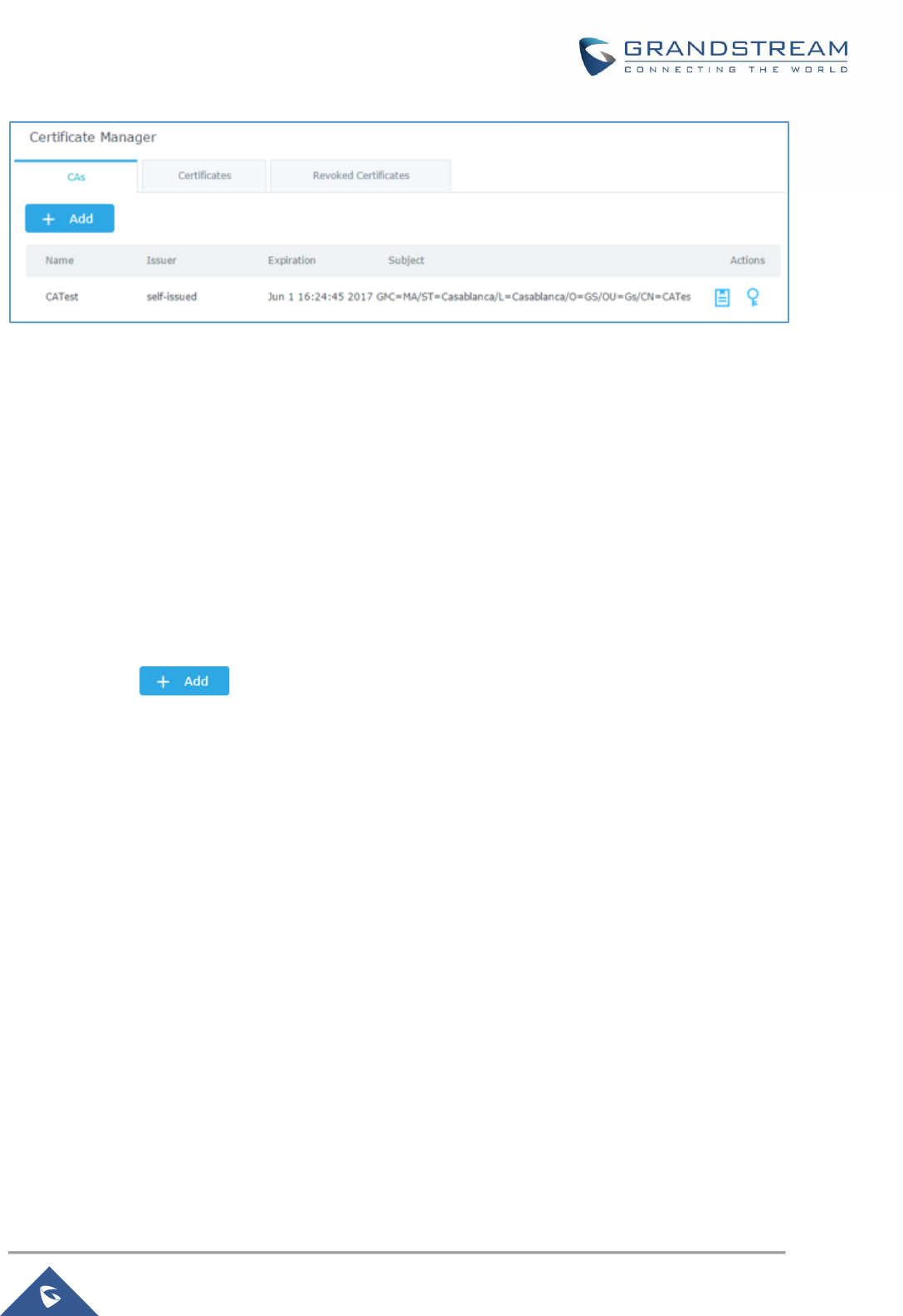
P a g e | 80
GWN7000 User Manual
Version 1.0.9.6
Figure 50: CA Certificate
Generate Server/Client Certificates
Create both server and client certificates for encrypted communication between clients and GWN7000
acting as an OpenVPN® server.
Creating Server Certificate
To create server certificate, follow below steps:
1. Navigate to “System Settings→Cert. Manager→Certificates”.
2. Click on button. A popup window will appear.
Refer to below figure showing an example of configuration and below table showing all available
options with their respective description.
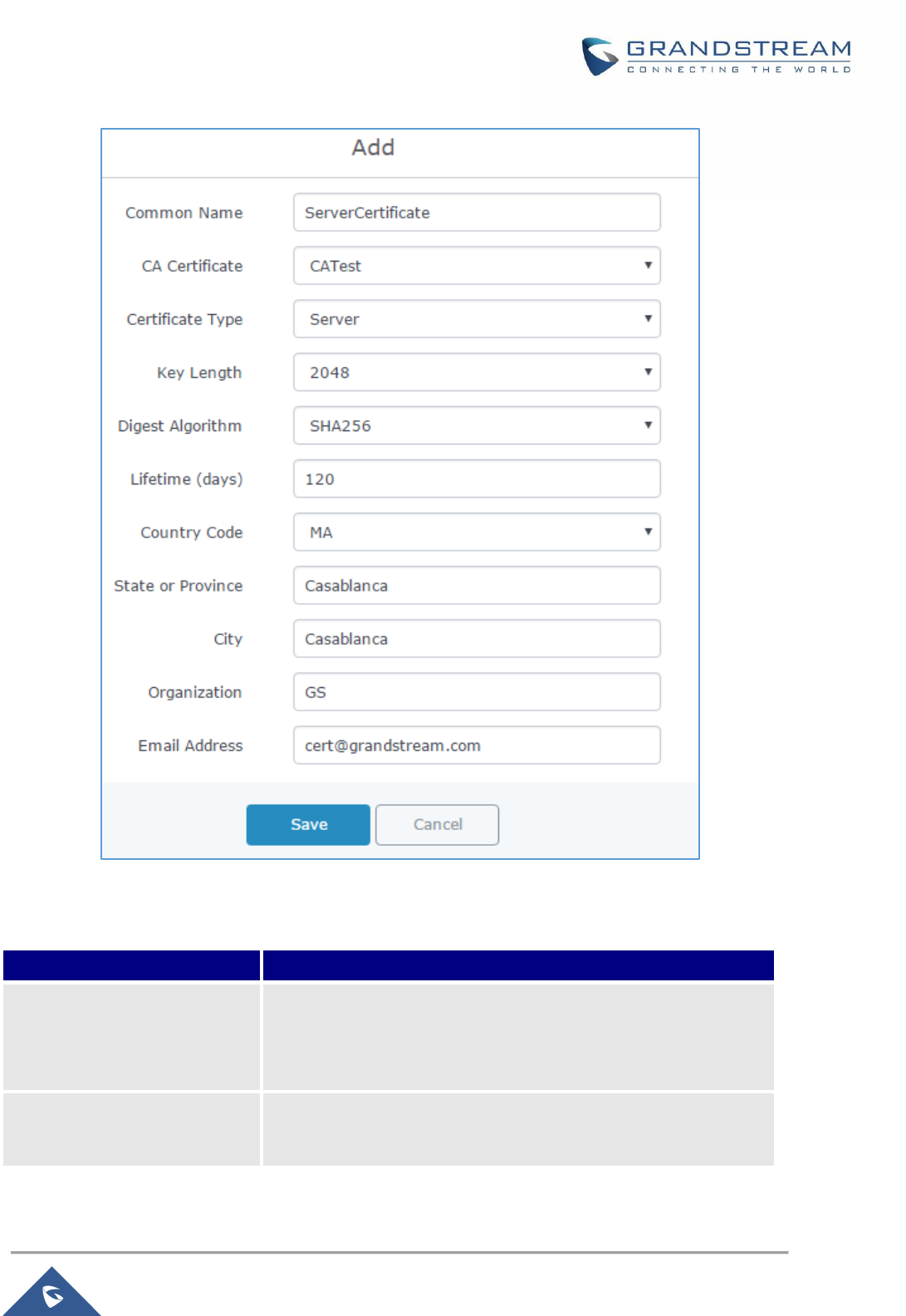
P a g e | 81
GWN7000 User Manual
Version 1.0.9.6
Figure 51: Generate Server Certificates
Table 26: Server Certificate
Field
Description
Common Name
Enter the common name for the server certificate.
It could be any name to identify this certificate.
Example: “ServerCertificate”.
CA Certificate
Select CA certificate previously generated from the drop-down list.
Example: “CATest”.

P a g e | 82
GWN7000 User Manual
Version 1.0.9.6
Certificate Type
Choose the certificate type from the drop-down list. It can be either
a client or a server certificate.
Choose “Server” to generate server certificate.
Key Length
Choose the key length for generating the server certificate.
Following values are available:
• 1024: 1024-bit keys are no longer sufficient to protect
against attacks. Not recommended.
• 2048: 2048-bit keys are a good minimum. Recommended.
• 4096: 4096-bit keys are accepted by nearly all RSA
systems. Using 4096-bit keys will dramatically increase
generation time, TLS handshake delays, and CPU usage
for TLS operations.
Digest Algorithm
Choose the digest algorithm:
• SHA1: This digest algorithm provides a 160-bit fingerprint
output based on arbitrary length input.
• SHA-256: This digest algorithm generates an
almost-unique, fixed size 256-bit (32-byte) hash. Hash is a
one-way function – it cannot be decrypted back
Lifetime (days)
Enter the validity date for the server certificate in days.
In our example, set to “120”.
Country Code
Select a country code from the dropdown list.
Example: “MA”.
State or Province
Enter a state name or province.
Example: “Casablanca”.
City
Enter a city name.
Example: “Casablanca”.
Organization
Enter the organization name.
Example: “GS”.
Email Address
Enter an email address.
Example: “Cert@grandstream.com”.
3. Click on button after completing all the fields for the server certificate.
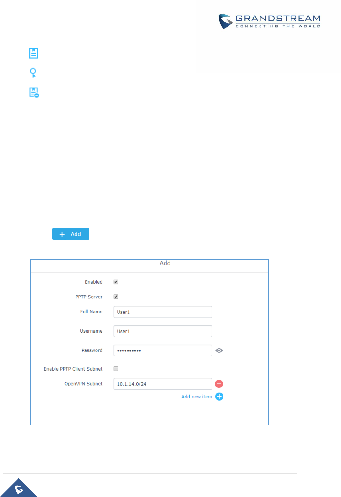
P a g e | 83
GWN7000 User Manual
Version 1.0.9.6
Click on button to export the server certificate file in “.crt” format.
Click on button to export the server key file in “. key” format.
Click on button to revoke the server certificate if no longer needed.
Notes:
• The server certificates (.crt and .key) will be used by the GWN7000 when acting as a server.
• The server certificates (.crt and .key) can be exported and used on another OpenVPN® server.
Creating Client Certificate
To create client certificate, follow below steps:
1- Create Users
a. Navigate to “System Settings→User Manager”.
b. Click on button. The following window will pop up.
Figure 52: User Management
c. Enter User information based on below descriptions.
P a g e | 84
GWN7000 User Manual
Version 1.0.9.6
Field
Description
Enabled
Check to enable the user.
PPTP Server
Enable this option when using the account for PPTP client connection.
Full Name
Choose full name to identify the users.
Username
Choose username to distinguish client’s certificate.
Password
Enter user password for each username.
Enable PPTP Client
Subnet
Enable this option to configure the remote subnet reachable through the
PPTP client.
Client Subnet
Enter the Subnet that exists behind the connected PPTP client.
OpenVPN Subnet
Used to indicate which networks are located behind the remote device
when the user account is used by an OpenVPN client router to establish
a site-to-site VPN.
d. Repeat above steps for each user.
2- Create Client Certificate
a. Navigate under “System Settings→Cert. Manager→Certificates”.
b. Click on button. The following window will pop up.
c. Enter client certificate information based on below descriptions.
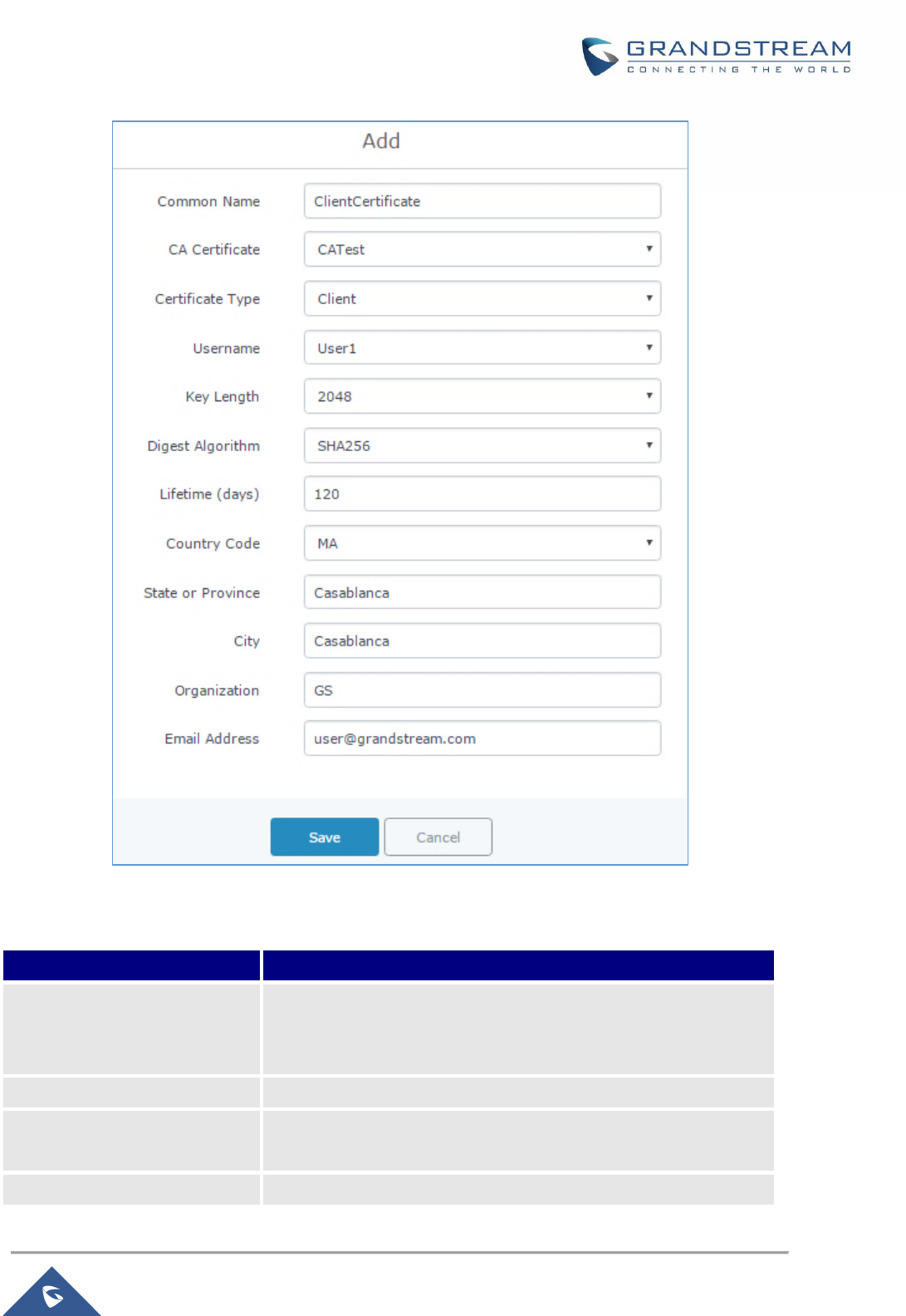
P a g e | 85
GWN7000 User Manual
Version 1.0.9.6
Figure 53: Client Certificate
Table 27: Client Certificate
Field
Description
Common Name
Enter the common name for the client certificate.
It could be any name to identify this certificate.
Example: “ClientCertificate”.
CA Certificate
Select the generated CA certificate from the drop-down list.
Certificate Type
Choose the certificate type from the drop-down list.
It can be either a client or server certificate.
Username
Select created user to generate his certificate.

P a g e | 86
GWN7000 User Manual
Version 1.0.9.6
Key Length
Choose the key length for generating the client certificate.
Following values are available:
• 1024: 1024-bit keys are no longer sufficient to protect
against attacks. Not recommended.
• 2048: 2048-bit keys are a good minimum. Recommended.
• 4096: 4096-bit keys are accepted by nearly all RSA
systems. Using 4096-bit keys will dramatically increase
generation time, TLS handshake delays, and CPU usage
for TLS operations.
Digest Algorithm
Choose the digest algorithm:
• SHA1: This digest algorithm provides a 160-bit fingerprint
output based on arbitrary length input.
• SHA-256: This digest algorithm generates an
almost-unique, fixed size 256-bit (32-byte) hash. Hash is a
one-way function – it cannot be decrypted back
Lifetime (days)
Enter the validity date for the client certificate in days.
Example: “120”.
Country Code
Select a country code from the dropdown list.
Example: “MA”.
State or Province
Enter a state name or province.
Example: “Casablanca”.
City
Enter a city name.
Example: “Casablanca”.
Organization
Enter the organization name.
Example: “GS”.
Email Address
Enter an email address.
Example: “user@grandstream.com”.
d. Click on after completing all the fields for the client certificate.
e. Click on to export the client certificate file in “.crt” format.
f. Click on to export the client key file in “.key” format.

P a g e | 87
GWN7000 User Manual
Version 1.0.9.6
Click on to revoke the client certificate if no longer needed.
The client certificates (“.crt” and “.key”) will be used by clients connected to the GWN7000 in order to
establish TLS handshake.
Notes:
• Client certificates generated from the GWN7000 need to be uploaded to the clients.
• For security improvement, each client needs to have his own username and certificate, this way
even if a user is compromised, other users will not be affected.
Create OpenVPN® Server
Once client and server certificates are successfully created, you can create a new server, so that clients
can be connected to it, by navigating under “VPN→OpenVPN®→Server”.
To create a new VPN server, follow below steps:
1. Click on and the following window will pop up.

P a g e | 88
GWN7000 User Manual
Version 1.0.9.6
Figure 54: Create OpenVPN® Server

P a g e | 89
GWN7000 User Manual
Version 1.0.9.6
Table 28: OpenVPN® Server
Field
Description
Enable
Click on the checkbox to enable the OpenVPN® server feature.
VPN Name
Enter a name for the OpenVPN® server.
Server Mode
Choose the server mode the OpenVPN® server will operate with.
4 modes are available:
• PSK: Used to establish a point-to-point OpenVPN®
configuration. A VPN tunnel will be created with a server
endpoint of a specified IP and a client endpoint of specified IP.
Encrypted communication between client and server will occur
over UDP port 1194, the default OpenVPN® port.
• SSL: Authentication is made using certificates only (no
user/pass authentication). Each user has a unique client
configuration that includes their personal certificate and key.
This is useful if clients should not be prompted to enter a
username and password, but it is less secure as it relies only
on something the user has (TLS key and certificate).
• User Auth: Authentication is made using only CA, user and
password, no certificates. Useful if the clients should not have
individual certificates.
Less secure as it relies on a shared TLS key plus only
something the user knows (Username/password).
• SSL + User Auth: Requires both certificate and username /
password. Each user has a unique client configuration that
includes their personal certificate and key.
Most secure as there are multiple factors of authentication
(TLS Key and Certificate that the user has, and the
username/password they know).
Protocol
Choose the Transport protocol from the dropdown list, either TCP or
UDP. The default protocol is UDP.
Bind to Local Interface
Select the interface used to connect the GWN7000 to the uplink,
either WAN1, WAN2, LAN or All.

P a g e | 90
GWN7000 User Manual
Version 1.0.9.6
Local Port
Configure the listening port for OpenVPN® server. The default
value is 1194.
Traffic Routing Policy
Select which routing policy to assign to the traffic from this VPN
network.
See Policy Routing section in the GWN7000 usermanual.
Destination
Choose to which destination group or WAN to allow traffic from the
VPN, this will generate automatically a forwarding rule under the
menu Firewall → Traffic Rules → Forward.
Encryption Algorithm
Choose the encryption algorithm from the dropdown list to encrypt
data so that the receiver can decrypt it using same algorithm.
Digest Algorithm
Choose digest algorithm from the dropdown list, which will uniquely
identify the data to provide data integrity and ensure that the
receiver has an unmodified data from the one sent by the original
host.
TLS Authentication
This option uses a static Pre-Shared Key (PSK) that must be
generated in advance and shared among all peers.
This feature adds extra protection to the TLS channel by requiring
that incoming packets have a valid signature generated using the
PSK key.
TLS Pre-Shared Key
Enter the generated TLS Pre-Shared Key when using TLS
Authentication.
Certificate Authority
Select a generated CA from the dropdown list.
Server Certificate
Select a generated Server Certificate from the dropdown list.
IPv4 Tunnel Network
Enter the network range that the GWN7000 will be serving from to
the OpenVPN® client.
Note: The network format should be the following 10.0.10.0/16.
The mask should be at least 16 bits.
Redirect Gateway
When redirect-gateway is used, OpenVPN® clients will route DNS
queries through the VPN, and the VPN server will need to handle
them.
Automatic Firewall Rule
Enable automatic firewall rule.
Push Route
Specify route(s) to be pushed to all clients. Example: 10.0.0.1/8
LZO Compression
Select whether to activate LZO compression or no, if set to
“Adaptive”, the server will make the decision whether this option will
be enabled or no.
P a g e | 91
GWN7000 User Manual
Version 1.0.9.6
Allow Peer to Change IP
Allow remote change the IP and/or Port, often applicable to the
situation when the remote IP address changes frequently.
2. Click after completing all the fields.
3. Click on top of the WebGUI in order to apply changes.
Figure 55: OpenVPN®
OpenVPN® Client Configuration
There are two ways to use the GWN7000 as an OpenVPN® client:
1) Upload client certificate created from an OpenVPN® server to GWN7000.
2) Create client/server certificates on GWN7000 and upload server certificate to the OpenVPN® server.
Go to “VPN→OpenVPN®→Client” and follow steps below:
1. Click on and the following window will pop up.
P a g e | 92
GWN7000 User Manual
Version 1.0.9.6
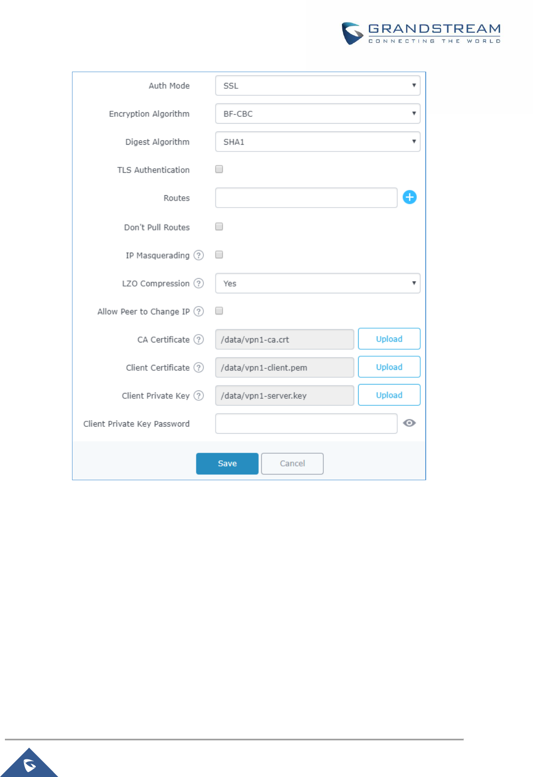
P a g e | 93
GWN7000 User Manual
Version 1.0.9.6
Figure 56: OpenVPN® Client

P a g e | 94
GWN7000 User Manual
Version 1.0.9.6
Table 29: OpenVPN® Client
Field
Description
Enable
Click on the checkbox to enable the OpenVPN® client feature.
VPN Name
Enter a name for the OpenVPN® client.
Protocol
Choose the Transport protocol from the dropdown list, either TCP or
UDP. The default protocol is UDP.
Bind to Local
Select the interface used to connect the GWN7000 to the uplink,
either WAN1, WAN2, LAN or All.
Interface
Select the interface used to connect the GWN7000 to the uplink,
either WAN1, WAN2.
Local Port
Configure the listening port for OpenVPN® server. Default is 1194.
Destination
Choose to which destination group or WAN to allow traffic from the
VPN, this will generate automatically a forwarding rule under the
menu Firewall → Traffic Rules → Forward.
Remote OpenVPN® Server
Configure the remote OpenVPN® server IP address.
Remote OpenVPN® Server
Port
Configure the remote OpenVPN® server port.
Local TUN IP address
Configures statically the local VPN tunnel IP address for the client.
Remote TUN IP address
Configures statically the local VPN tunnel IP address for the remote
server.
Auth Mode
Choose the server mode the OpenVPN® server will operate with, 4
modes are available:
• PSK: used to establish a point-to-point OpenVPN®
configuration. A VPN tunnel will be created with a server
endpoint of a specified IP and a client endpoint of specified IP.
Encrypted communication between client and server will occur
over UDP port 1194, the default OpenVPN® port.
• SSL: Authentication is made using certificates only (no
user/pass authentication). Each user has a unique client
configuration that includes their personal certificate and key.
This is useful if clients should not be prompted to enter a
username and password, but it is less secure as it relies only
on something the user has (TLS key and certificate).
• User Auth: Authentication is made using only CA, user and
password, no certificates. Useful if the clients should not have
individual certificates.

P a g e | 95
GWN7000 User Manual
Version 1.0.9.6
Less secure as it relies on a shared TLS key plus only
something the user knows (Username/password).
• SSL + User Auth: Requires both certificate and username /
password. Each user has a unique client configuration that
includes their personal certificate and key.
Most secure, as there are multiple factors of authentication
(TLS Key and Certificate that the user has, and the
username/password they know).
Encryption Algorithm
Choose the encryption algorithm from the drop-down list, in order to
encrypt data so that the receiver can decrypt it using the same
algorithm.
Digest Algorithm
Choose the digest algorithm from the drop-down list, which will
uniquely identify the data to provide data integrity and ensure that
the receiver has an unmodified data from the one sent by the
original host.
TLS Authentication
This option uses a static Pre-Shared Key (PSK) that must be
generated in advance and shared among all peers. This feature
adds extra protection to the TLS channel by requiring that incoming
packets have a valid signature generated using the PSK key.
TLS Pre-Shared Key
Enter the generated TLS Pre-Shared Key when using TLS
Authentication.
Routes
This feature allows specifying and adding custom routes.
Don’t Pull Routes
If enabled, client will ignore routes pushed by the server.
IP Masquerading
This feature is a form of network address translation (NAT) which
allows internal computers with no known address outside their
network, to communicate to the outside. It allows one machine to
act on behalf of other machines.
LZO Compression
LZO encoding provides a very high compression ratio with good
performance. LZO encoding works especially well for CHAR and
VARCHAR columns that store very long character strings.
Allow Peer to Change IP
Allow remote change the IP and/or Port, often applicable to the
situation when the remote IP address changes frequently.
CA Certificate
Click on “Upload” and select the “CA” certificate generated
previously on this guide.
Client Certificate
Click on “Upload” and select the “Client Certificate” generated
previously on this guide.
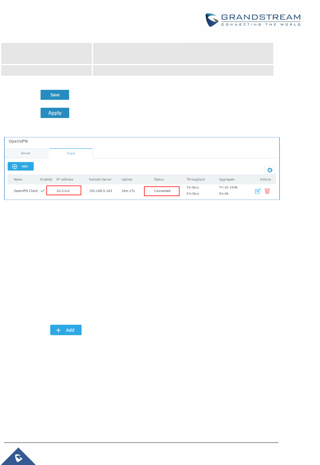
P a g e | 96
GWN7000 User Manual
Version 1.0.9.6
Client Private Key
Click on “Upload” and select the “Client Private Key” generated
previously on this guide.
Client Private Key Password
Enter the client private key password
2. Click after completing all the fields.
3. Click on top of the web GUI to apply changes.
Figure 57: OpenVPN® Client
L2TP/IPSEC Configuration
Layer 2 Tunneling Protocol (L2TP) is a tunneling protocol used to support virtual private networks (VPNs)
or as part of the delivery of services by ISPs. It does not provide any encryption or confidentiality by itself.
Rather, it relies on an encryption protocol that it passes within the tunnel to provide privacy.
GWN7000 L2TP/IPSec Client Configuration
To configure L2TP client on the GWN7000, navigate under “VPN→L2TP/IPSec” and set the following:
1- Click on and the following window will pop up.
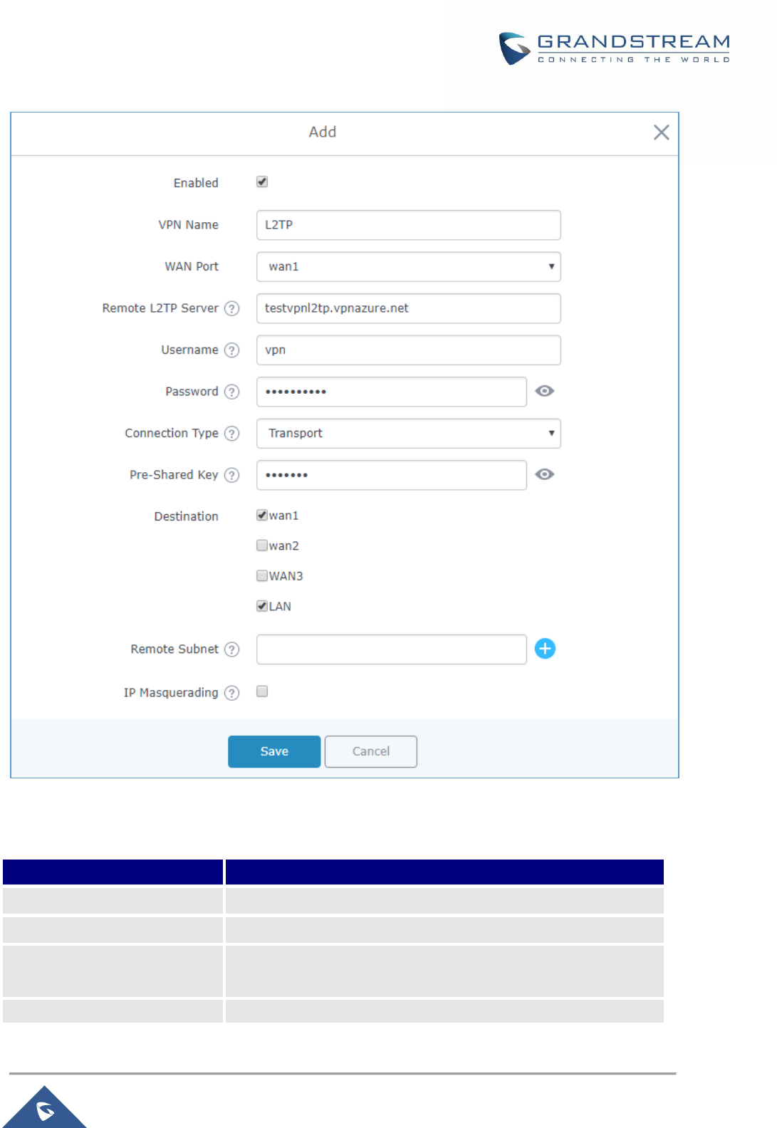
P a g e | 97
GWN7000 User Manual
Version 1.0.9.6
Figure 58: L2TP Client Configuration
Table 30: L2TP Configuration
Field
Description
Enable
Click on the checkbox in order to enable the L2TP client feature.
VPN Name
Enter a name for the L2TP client.
WAN Port
Select which WAN port is connected to the uplink, either WAN1 or
WAN2.
Remote L2TP Server
Enter the IP/Domain of the remote L2TP Server.

P a g e | 98
GWN7000 User Manual
Version 1.0.9.6
Username
Enter the Username for authentication against the VPN Server.
Password
Enter the Password for authentication against the VPN Server.
Connection Type
Select either Transport mode or Tunnel mode:
• Transport mode is commonly used between end stations
or between an end station and a gateway, if the gateway is
being treated as a host.
• Tunnel mode is used between gateways, or at an end
station to a gateway, the gateway acting as a proxy for the
hosts behind it.
Pre-Shared Key
Enter the L2TP pre-shared key.
Remote Subnet
Configures the remote subnet for the VPN.
The format should be “IP/Mask” where IP could be either IPv4 or
IPv6 and mask is a number between 1 and 32.
For example: 192.168.5.0/24
IP Masquerading
This feature is a form of network address translation (NAT) which
allows internal computers with no known address outside their
network, to communicate to the outside. It allows one machine to
act on behalf of other machines.
Masq Source
This option allows the user to configure the local subnets that needs
to be masqueraded.
Use DNS from Server
Enable this option to retrieve DNS from the VPN server.
Keepalive
Specifies the keepalive failure value “n”. if ppp doesn’t receive LCP
response from “n” LCP echo-request frames, then the connection to
the peer will be terminated.
If this option is set LCP echo-request will be sent to the peer for
every 5 sec by default.
Use Built-in IPv6 management
Enable the IPv6 management for the VPN.
Connection retries
Configures the number of attempts to reconnect the L2TP client, if
this number is exceeded, the client will be disconnected from the
L2TP/IP Server.
2- Click after completing all the fields.
3- Click on top of the web GUI to apply changes.
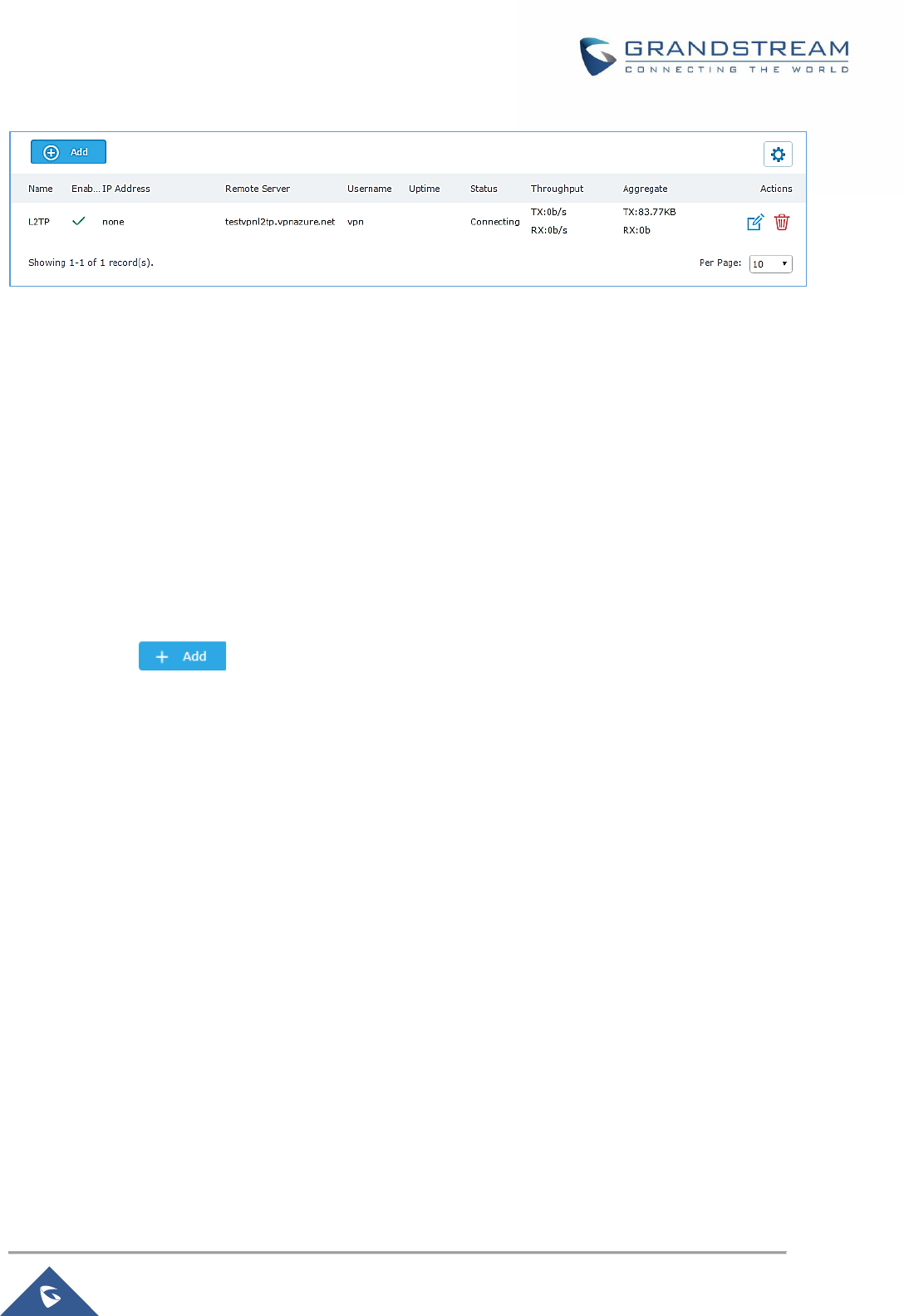
P a g e | 99
GWN7000 User Manual
Version 1.0.9.6
Figure 59: L2TP Client
PPTP CONFIGURATION
A data-link layer protocol for wide area networks (WANs) based on the Point-to-Point Protocol (PPP) and
developed by Microsoft that enables network traffic to be encapsulated and routed over an unsecured
public network such as the Internet. Point-to-Point Tunneling Protocol (PPTP) allows the creation of virtual
private networks (VPNs), which tunnel TCP/IP traffic through the Internet.
GWN7000 Client Configuration
To configure PPTP client on the GWN7000, navigate under “VPN→PPTP” and set the following:
1- Click on and the following window will pop up.
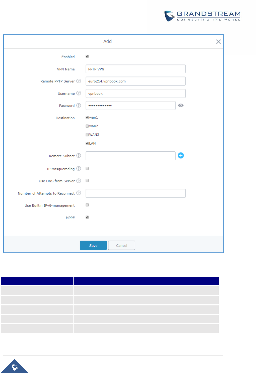
P a g e | 100
GWN7000 User Manual
Version 1.0.9.6
Figure 60: PPTP Client Configuration
Table 31: PPTP Configuration
Field
Description
Enable
Click on the checkbox to enable the PPTP VPN client feature.
VPN Name
Enter a name for the PPTP client.
Remote PPTP Server
Enter the IP/Domain of the remote PPTP Server.
Username
Enter the Username for authentication against the VPN Server.
Password
Enter the Password for authentication against the VPN Server.
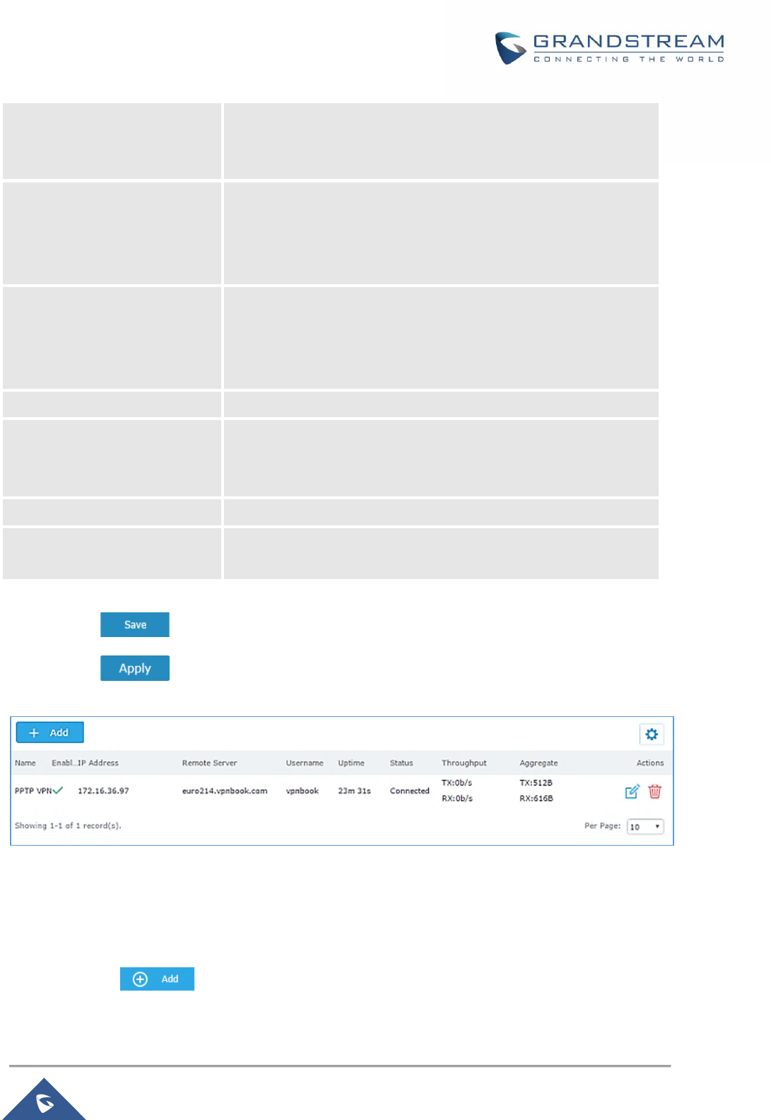
P a g e | 101
GWN7000 User Manual
Version 1.0.9.6
Destination
Choose to which destination group or WAN to allow traffic from the
VPN, this will generate automatically a forwarding rule under the
menu Firewall → Traffic Rules → Forward.
Remote Subnet
Configures the remote subnet for the VPN.
The format should be “IP/Mask” where IP could be either IPv4 or
IPv6 and mask is a number between 1 and 32.
For example: 192.168.5.0/24
IP Masquerading
This feature is a form of network address translation (NAT) which
allows internal computers with no known address outside their
network, to communicate to the outside. It allows one machine to
act on behalf of other machines.
Use DNS from Server
Enable this option to retrieve DNS from the VPN server.
Number of Attempts to
Reconnect
Configures the number of attempts to reconnect the PPTP client, if
this number is exceeded, the client will be disconnected from the
PPTP Server.
Use Built-in IPv6 management
Enable the IPv6 management for the VPN.
MPPE
Enable / disable the MPPE for data encryption. By default, it’s
disabled.
2- Click after completing all the fields.
3- Click on top of the web UI to apply changes.
Figure 61: PPTP Client
GWN7000 PPTP Server Configuration
To configure PPTP server on the GWN7000, go to “VPN→PPTP→Server” and set the following:
1- Click on and the following window will pop up.
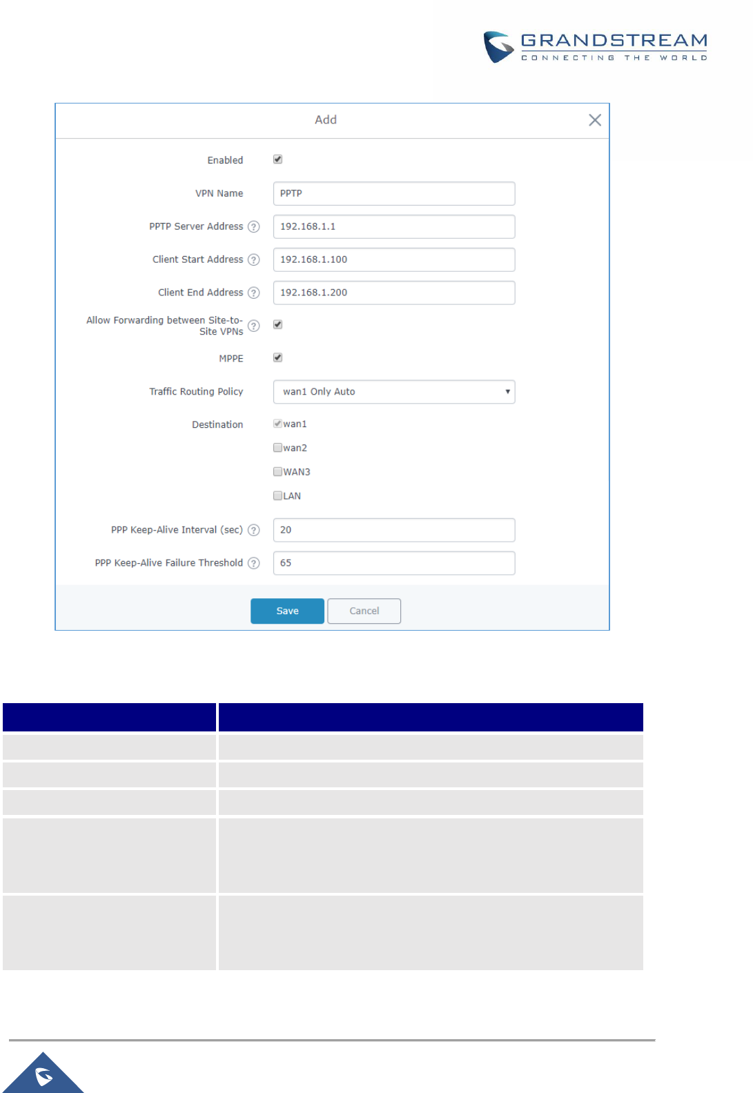
P a g e | 102
GWN7000 User Manual
Version 1.0.9.6
Figure 62: PPTP Server Configuration
Table 32: PPTP Server Configuration Parameters
Field
Description
Enable
Click on the checkbox to enable the PPTP VPN Server.
VPN Name
Enter a name for the PPTP Server.
PPTP Server Address
Configure the PPTP server local address (ex: 192.168.1.1).
Client Start Address
Configure the remote client IP start address.
Note: this address should be in the same subnet as the end
address and PPTP server address.
Client End Address
Configure the remote client IP end address.
Note: this address should be in the same subnet as the start
address and PPTP server address.

P a g e | 103
GWN7000 User Manual
Version 1.0.9.6
Allow Forwarding between
Site-To-Site VPNs
This option allows forwarding between multiple site-to-site VPNs.
i.e. if there are multiple PPTP users configured with client subnet
enabled, then this option allows one PPTP client subnet to access
another PPTP client subnet through the server.
Note: for this option to work more than one PPTP users with client
subnet must be enabled.
MPPE
Enable / disable the MPPE for data encryption. By default, it’s
disabled.
Traffic Routing Policy
Select which routing policy to assign to the traffic from this VPN
network. See Policy Routing section
Destination
Choose to which destination group or WAN to allow traffic from the
VPN, this will generate automatically a forwarding rule under the
menu Firewall → Traffic Rules → Forward.
PPP Keep-Alive Interval (sec)
Interval in seconds for LCP echo-request frames to be sent.
PPP Keep-Alive Failure
Threshold
The PPTP server will consider a peer to be dead if N Echo-request
frames aren’t replied to. The connection will be then terminated.
A setting of 0 disables this function.
PPP Adaptive Keep-Alive
If the PPP keepalive failure settings is enabled, then echo-request
frames will only be sent if no traffic has been received from the
peers since the last echo-request was sent.
Debug
Enable debug logging to syslog.
MTU
Specify the MTU, valid range (1280-1500 Bytes).
MRU
Specify the MRU, valid range (1280-1500 Bytes).
2- Click after completing all the fields.
3- Click on top of the web GUI to apply changes.
After this step, you need to create user accounts under web GUI → System Settings → User Manager in
order to connected to the configured PPTP server.

P a g e | 104
GWN7000 User Manual
Version 1.0.9.6
IPSec VPN Tunnel
Overview
Internet Security protocol- IPsec is mainly used to authenticate and encrypt packets of data sent over the
network layer. In order to accomplish this, they use two security protocols - ESP (Encapsulation Security
Payload) and AH (Authentication Header), the former provides both authentication as well as encryption
whereas the latter provides only authentication for the data packets. Since both authentication and
encryption are equally desirable, most of the implementations use ESP.
IPsec supports two different encryption modes, they are Tunnel (default) and the Transport mode. Tunnel
mode is used to encrypt both payload as well as the header of an IP packet, which is considered to be
more secure. Transport mode is used to encrypt only the payload of an IP packet, which is generally used
in gateway or host implementations.
IPsec also involves IKE (Internet Key Exchange) protocol which is used to setup the Security Associations
(SA). A Security Association establishes a set of shared security parameters between two network entities
to provide a secure network layer communication. These security parameters may include: the
cryptographic algorithm and mode, traffic encryption key and parameters for the network data to be sent
over the connection. Currently there are two IKE versions available – IKEv1 and IKEv2. IKE works in two
phases:
- Phase 1: ISAKMP operations will be performed after a secure channel is established between two
network entities.
- Phase 2: Security Associations will be negotiated between two network entities.
IKE operates in three modes for exchanging of keying information and establishing security associations –
Main, Aggressive and Quick mode.
- Main mode: is used to establish the phase 1 during the key exchange. It uses three two-way
exchanges between the initiator and the receiver. In the first exchange, algorithms and hashes are
exchanged. In the second exchange, shared keys are generated using Diffie-Hellman exchange.
In the last exchange, verification of each other’s identities takes place.
- Aggressive mode: provides the same service as the main mode, but it uses two exchanges
instead of three. It does not provide identity protection, which makes it vulnerable to hackers. Main
mode is more secure than this.
- Quick mode: After establishing a secure channel using either main mode or aggressive mode,
quick mode can be used to negotiate general IPsec security services and to generate newly keyed
material. They are always encrypted under the secure channel and uses the hash payload that is
used to authenticate the rest of the packet.
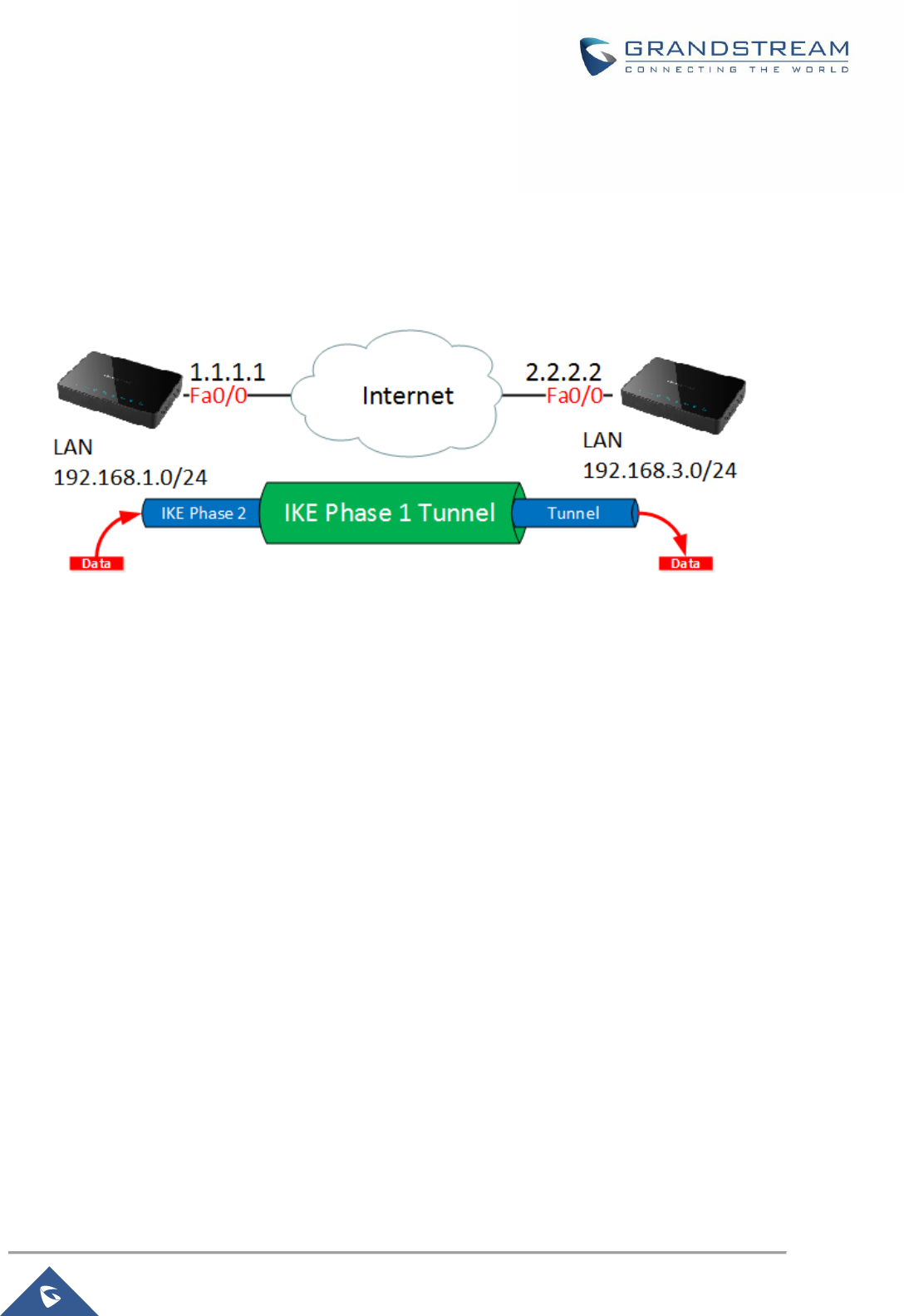
P a g e | 105
GWN7000 User Manual
Version 1.0.9.6
Configuring GWN7000 IPSec Tunnel
In order to build an IPSec secure tunnel between two devices located on different places on the Internet,
we can use the sample scenario below:
Branch office router needs to connect to Headquarters office via an IPSec tunnel, on each side we have a
GWN7000 router. Users can configure the two devices as following:
The branch office router runs a LAN subnet 192.168.1.0/24 and the HQ router runs a LAN subnet
192.168.3.0, the public IP of the branch office router is 1.1.1.1 and the IP of the HQ router is 2.2.2.2.
Configuration of Branch office router:
Go under VPN → IPSec then click on add and fill in the following information under phase 1 tab:
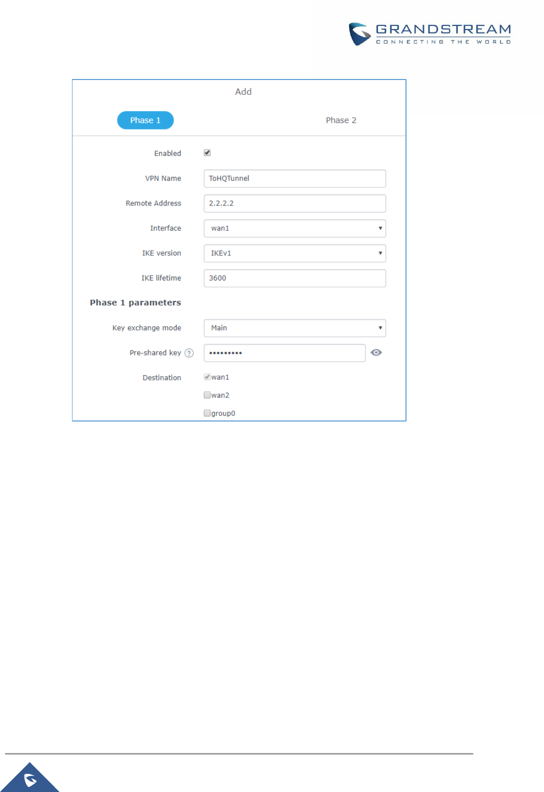
P a g e | 106
GWN7000 User Manual
Version 1.0.9.6
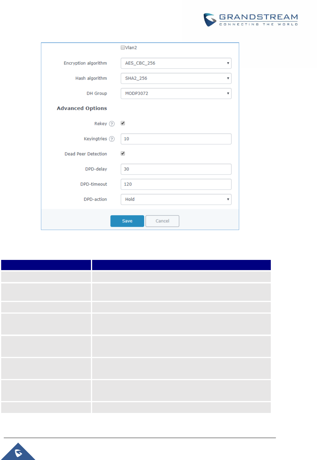
P a g e | 107
GWN7000 User Manual
Version 1.0.9.6
Figure 63: Branch Office IPSec Phase 1 Configuration
Table 33: IPSec Phase 1 Parameters
Field
Description
Enabled
Enable or Disable the IPSec tunnel.
VPN Name
VPN Connection Name.
Remote Address
Enter the IP address of the remote side of the tunnel.
Interface
Select from which interface the router will try to build the VPN
connection.
IKE Version
Allows the use to choose between using IKE version 1 or 2.
Default value: IKEv1
IKE Lifetime
Specifies in seconds the lifetime of the keying channel.
Default: 3600 seconds.
Key Exchange mode
Select which mode to use for key exchange during the stage of
channel establishment: Main mode or Aggressive mode.
Pre-Shared key
Enter the PSK password for authentication.

P a g e | 108
GWN7000 User Manual
Version 1.0.9.6
Destination
Choose to which destination group or WAN to allow traffic from the
VPN, this will generate automatically a forwarding rule under the
menu Firewall → Traffic Rules → Forward.
Encryption algorithm
Select the crypto to be used for data confidentiality:
• AES_CBC_256
• AES_CBC_192
• AES_CBC_128
• 3DES_192
Hash algorithm
Select the hash to be used data integrity:
• MD5
• SHA1
• SHA2_256
• SHA2_512
• SHA2_384
DH group
Select the Diffie Hellman group to be used for the session:
• MODP1024
• MODP1536
• MODP2048
• MODP3072
• MODP4096
• MODP6144
• MODP8192
• DH19
• DH20
• DH21
• DH23
• DH24
Rekey
This allows the user to decide whether a connection should be
renegotiated when it is about to expire. if disabled it is necessary to
make sure the other end also agrees on it. Otherwise it is
ineffective.
Keying tries
This specifies the number of attempts to be made to negotiate a
connection before giving up. By default, it is set to 10 and if set to 0
the router will keep trying forever.
Dead Peer Detection
Check the option to enable/disable DPD.

P a g e | 109
GWN7000 User Manual
Version 1.0.9.6
DPD delay
Configures the delay for DPD keepalive packets for the specific
connection.
DPD timeout
Configures the length of time it will remain idle without
receiving any response from the peer.
DPD action
This provides the user with a set of actions to perform if the peer is
considered to be dead.
• hold- all routes will be put on hold
• clear- routes and SA will be cleared.
• restart-all SA’s to the dead peer will be renegotiated.
Press Save, then go to phase2 tab in order to configure the phase 2 parameters as folllow
Figure 64:Branch Router IPSec Phase 2 Configuration
After this is done, press save and apply the settings, then configure same settings for phase 1 on the HQ
router, as for phase 2 configuration parameters they should be as following:
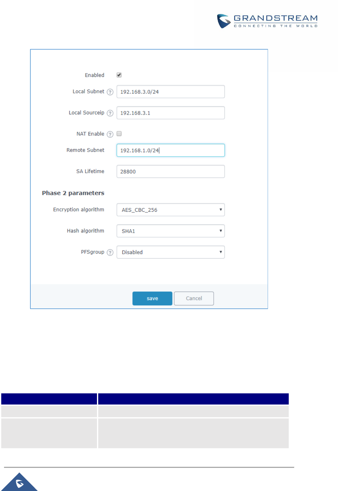
P a g e | 110
GWN7000 User Manual
Version 1.0.9.6
Figure 65: HQ Router IPSec Phase 2 Configuration
Once this is done, the two routers will build the tunnel and the necessary routing information in order to
route traffic through the tunnel back and from the branch office to HQ network.
For reference, the table below gives the descriptions of the parameters used for phase 2 settings:
Table 34: IPSec Phase 2 Parameters
Field
Description
Local Subnet
Configure the local subnet that will be included on the connection.
Local Source IP
Configures the source IP to be used when transmitting a packet to
the other end of the connection.

P a g e | 111
GWN7000 User Manual
Version 1.0.9.6
NAT Enable
This option enables the user to masquerade the local LAN subnets.
NAT translated subnet must be specified along with this option.
Remote Subnet
Specifies the remote subnet that can be reached through the tunnel
connection.
SA lifetime
Sets the lifetime of a set of encryption/auth keys for a packet.
Encryption algorithm
Select the crypto to be used for data confidentiality:
• AES_CBC_256
• AES_CBC_192
• AES_CBC_128
• 3DES_192
Hash algorithm
Select the hash to be used data integrity:
• MD5
• SHA1
• SHA2_256
PFS group
Select the Diffie Hellman group to be used for the session:
• MODP1024
• MODP1536
• MODP2048
• MODP3072
• MODP4096
• MODP6144
• MODP8192
• DH23
• DH24
The default value is disabled, which indicates that the router will use
the option configured on DH group under phase 1.
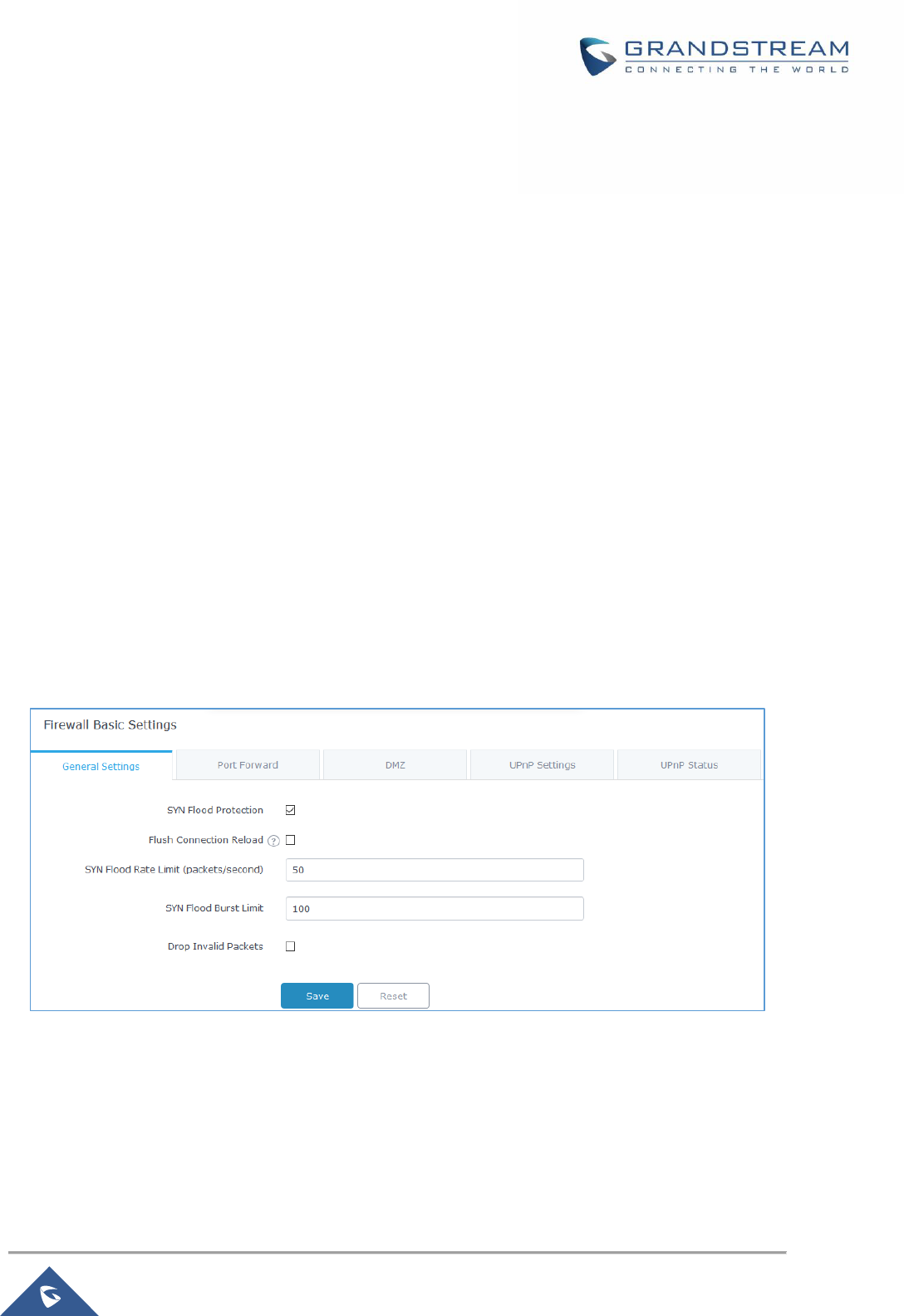
P a g e | 112
GWN7000 User Manual
Version 1.0.9.6
FIREWALL
GWN7000 supports firewall feature to control incoming and outgoing traffic by restricting or rejecting
specific traffic, as well as preventing attacks to the GWN7000 networks for enhanced security.
The Firewall feature includes 3 menus:
• Basic Settings: Used to enable SYN Flood, setup port forwarding, DMZ, inter-group traffic
forwarding and UPnP.
• Traffic Rules: Used to control incoming/outgoing traffic in customized scheduled times, and taking
actions for specified rules such as Accept; Reject and Drop.
• Advanced: Used to setup SNAT and DNAT.
Basic Settings
General Settings
SYN Flood Protection is used to avoid DOS attacks.
SYN Flood Protection is enabled by default on GWN7000, you can edit the “SYN Flood Rate Limit”, “SYN
Flood Burst Limit” and whether to drop or no the invalid packets as shown in the below screenshot
Figure 66: Basic → General Settings
Flush Connection Reload: When this option is enabled, and a firewall configuration change is made,
existing connections that had been permitted by the previous firewall rules will be terminated.
That way if the new firewall rules can’t permit a connection that had been previously established, it will be
terminated and won’t be able to reconnect.
When this option is disabled, existing connections are allowed to continue until they do timeout, even if the
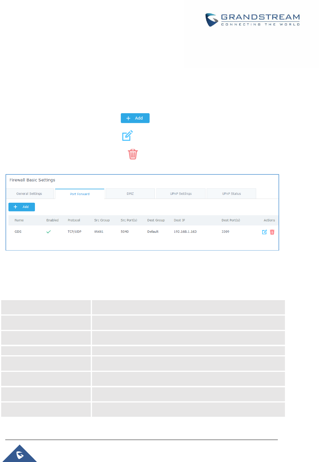
P a g e | 113
GWN7000 User Manual
Version 1.0.9.6
new rules wouldn’t allow these connections to be established.
Port Forwarding
Port forwarding allows redirecting a communication request from one address and port number
combination to another.
Below are different possible actions:
• To add a Port Forward rule, click on .
• To edit a Port Forward rule, click on .
• To delete a Port Forward rule, click on .
Figure 67: Port Forward
Refer to following table for Port Forwarding option when editing or creating a port-forwarding rule:
Table 35: Port Forward
Name
Specify a name for the port forward rule.
Enabled
Check to enable this port forward rule.
Protocol
Select a protocol, users can select TCP, UDP or TCP/UDP.
Source Group
Select the WAN Interface.
Source Port (s)
Set a single or a range of Ports.
Destination Group
Select the LAN or VLAN group.
Destination IP
Set the destination IP address.
Destination Port (s)
Set a single or a range of Ports.
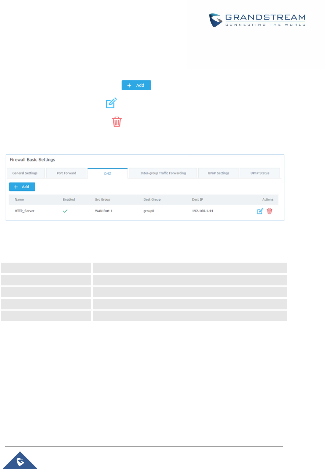
P a g e | 114
GWN7000 User Manual
Version 1.0.9.6
DMZ
GWN7000 support DMZ, where it is possible to specify a LAN client to be put on the DMZ.
• To add an IP into the DMZ, click on .
• To edit a DMZ entry, click on .
• To delete a DMZ entry, click on .
Figure 68: DMZ
Refer to below table for DMZ fields:
Table 36: DMZ
Name
Specify a name for the DMZ entry.
Enabled
Check to enable this DMZ entry.
Source Group
Select the WAN interface
Destination Group
Select the LAN group.
Destination IP
Set the destination IP address.
UPnP
GWN7000 supports UPnP that enables programs running on a host to configure automatically port
forwarding.
UPnP allows a program to make the GWN7000 to open necessary ports, without any intervention from the
user, without making any check.
UPnP settings can be accessed from GWN7000 WebGUI→Firewall→Basic→UPnP Settings.
Refer to below Table for UPnP settings.

P a g e | 115
GWN7000 User Manual
Version 1.0.9.6
Table 37: UPnP Settings
Enable Daemon
Check to enable Daemon for UPnP.
External Interface
Select the WAN interface to allow external connection to resources that
enables UPnP.
Internal Interface
Check the LAN network on which to activate UPnP.
Enable UPnP
Check to Enable UPnP for the LAN clients on selected LAN network.
Enable NAT-PMP
Check to enable automatic NAT Port Mapping (NAT-PMP).
Secure Mode
Check to activate secure mode for devices that activate UPnP.
Logging to Syslog
Choose whether to log activities for UPnP into Syslog.
Download Speed
Set the Download speed value in KB/s. Default is 2048
Upload Speed
Set the Upload speed value in KB/s. Default is 1024.
Users can check the UPnP status under the menu “Firewall → Basic → UPnP”.
Traffic Rules Settings
GWN7000 offers the possibility to fully control incoming/outgoing traffic for different protocols in
customized scheduled times and taking actions for specified rules such as Accept; Reject and Drop.
Following actions are available to configure Input, output and forward rules for configured protocols
• To add new rule, Click on .
• To edit a rule, Click on .
• To delete a rule, Click on .
Input
The GWN7000 allows to filter incoming traffic to networks group or port WAN1 or WAN2 and apply rules
such as:
• Accept: To allow the traffic to go through.
• Reject: A reply will be sent to the remote side stating that the packet is rejected.
• Drop: The packet will be dropped without any notice to the remote side.
P a g e | 116
GWN7000 User Manual
Version 1.0.9.6
Following actions are available to configure Input rules on the GWN7000 under “Firewall > Traffic Riles >
Input” for configured protocols.
• To add new rule, Click on
• To edit a rule, Click on
• To delete a rule, Click on
The following example rejects incoming ICMP request to WAN port 1, this means that whenever the
GWN7000 receives and incoming ICMP request on WAN port 1 the destination IP address will receive a
message stating that the destination IP address is unreachable.
Below screenshot shows configuration example:
Figure 69: INPUT Rule Sample

P a g e | 117
GWN7000 User Manual
Version 1.0.9.6
Output
The GWN7000 allows to filter outgoing traffic from the local LAN networks to outside networks and apply
rules such as:
• Accept: To allow the traffic to go through.
• Reject: A reply will be sent to the remote side stating that the packet is rejected.
• Drop: The packet will be dropped without any notice to the remote side.
Following actions are available to configure Output rules on the GWN7000 under “Firewall → Traffic
Rules → Output” for configured protocols.
• To add new rule, Click on
• To edit a rule, Click on
• To delete a rule, Click on
The following example will reject every outgoing ICMP request from GWN7000 to network Group1, this
means that whenever the GWN7000 receives an ICMP “echo-request” from another network group or from
WAN port 1 or 2 sent to LAN1 will be rejected.
Below screenshot shows configuration example:
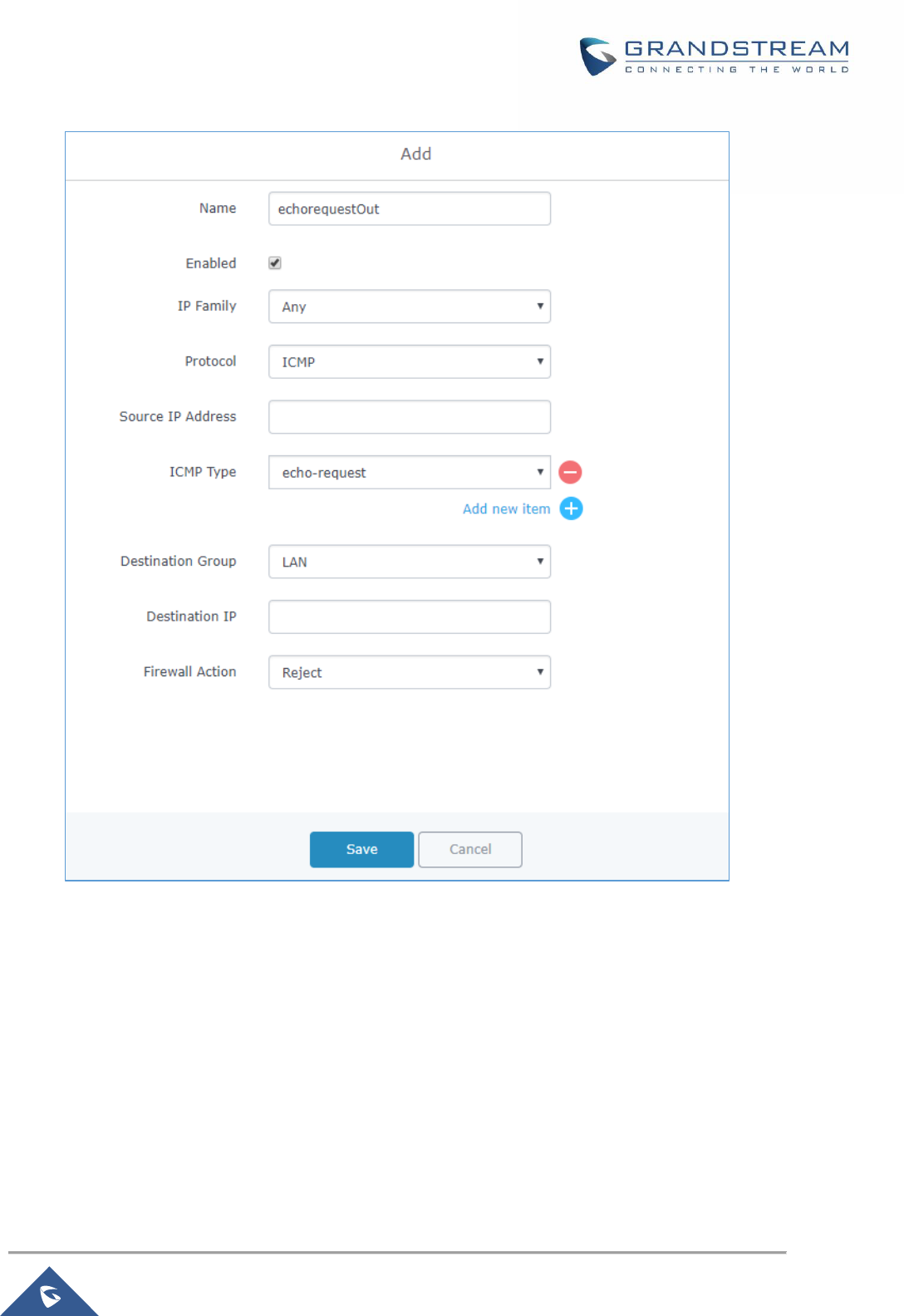
P a g e | 118
GWN7000 User Manual
Version 1.0.9.6
Figure 70: Output Rules Sample
GWN7000 offers the possibility to allow traffic between different groups and interfaces.
Users can select to edit a source group and add to it other network groups and WAN interfaces to allow
inter-group traffic between the selected members.
This will either use firewall rules or policy-based routing rules, if the action select is ACCEPT, DROP or
REJECT then the firewall rule will apply, otherwise if users want to trigger the policy-based routing, then
the action should be set to MATCH in order to match the traffic and apply the routing policy.
For further details, check the Policy Routing section.
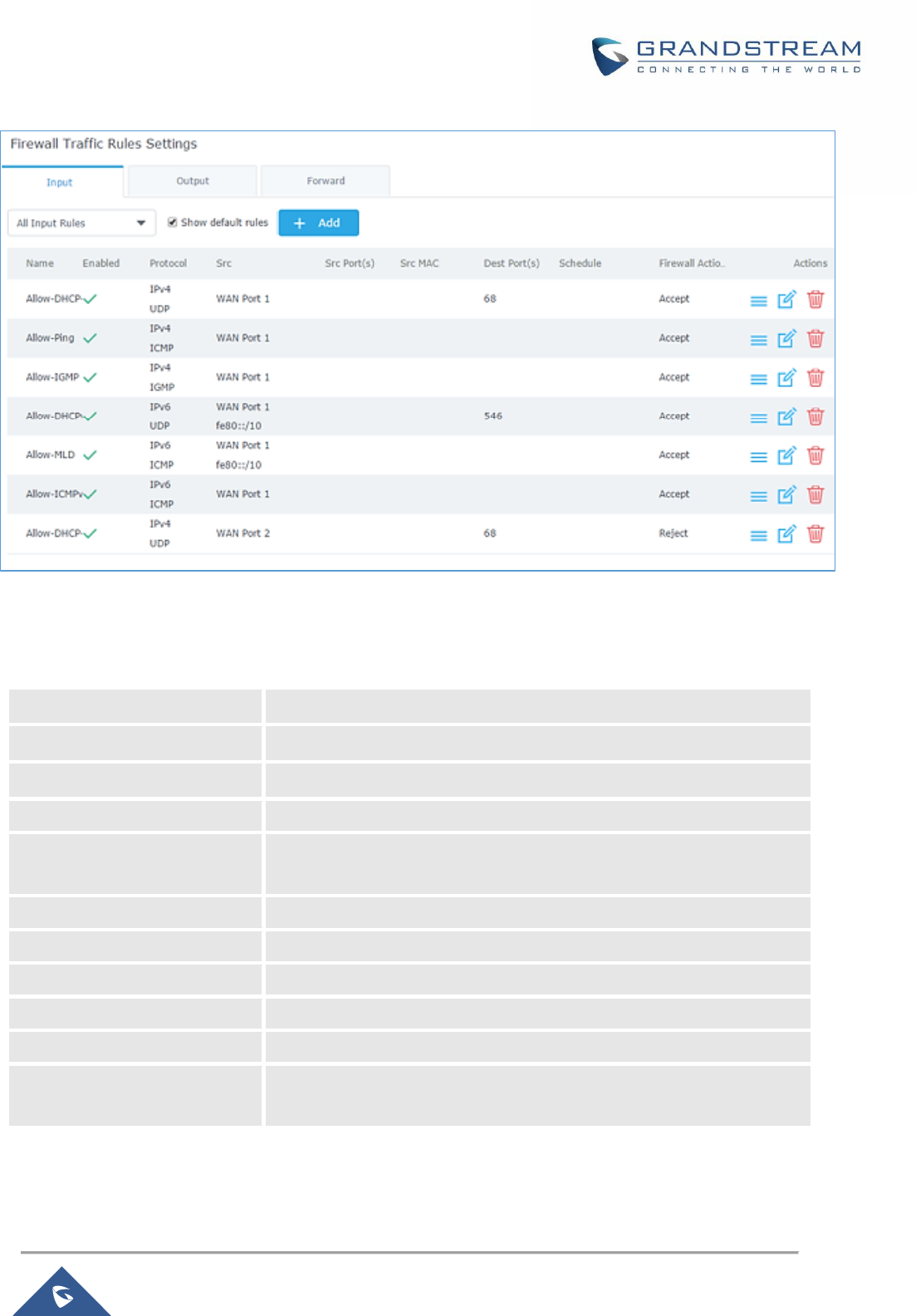
P a g e | 119
GWN7000 User Manual
Version 1.0.9.6
Figure 71: Traffic Rules Settings
Refer to below table for each tab, when editing or creating a traffic rule:
Table 38: Firewall Traffic Rules
Name
Specify a name for the traffic rule.
Enabled
Check to enable this rule.
IP Family
Select the IP version, three options are available: IPv4, IPv6 or Any.
Source Group
Select a WAN interface or a LAN group for Source Group, or select All.
Protocol
Select one of the protocols from dropdown list or All, available options
are: UDP, TCP, TCP/UCP, UDP-Lite, ICMP, AH, SCTP, IGMP and All.
Source IP Address
Set the Source IP address, it can be an IPv4 or IPv6 address.
Source Port(s)
Set the source port number. Or port range.
Source MAC address
Set the Source MAC address.
Destination IP
Set the destination IP address, it can be an IPv4 or IPv6 address.
Destination Port(s)
Set the destination’s port(s).
Firewall Action
Select which action to perform for the given traffic rule, 3 options are
available: Accept, Reject or Drop.

P a g e | 120
GWN7000 User Manual
Version 1.0.9.6
Firewall Advanced Settings
Firewall Advanced Settings page provides the ability to setup input/output policies for each WAN interface
and LAN groups; as well as setting configuration for Static and Dynamic NAT.
General Settings
Click on next to a WAN interface or Network group to edit its input and output policies.
Refer to below table for general settings options:
Table 39: Firewall-General Settings
Input Policy
Select which action to apply to all incoming traffic to this interface/LAN
group, 3 actions are available: Accept, Reject and Drop.
Output Policy
Select which action to apply to all outgoing traffic from this interface/LAN
group, 3 actions are available: Accept, Reject and Drop.
IP Masquerading
Check to enable IP Masquerading, this will allow internal computers with
no known address outside their network, to communicate to the outside.
It allows one machine to act on behalf of other machines.
MSS Clamping
Check to enable MSS Clamping. This will provide a method to prevent
fragmentation when the MTU value on the communication path is lower
than the MSS value.
Log Dropped and Reject
Traffic to Syslog
Check to send all rejected and dropped traffic logs to configured Syslog
Server.
Limit for Dropped and
Rejected Traffic
Specify the limit for dropped and reject traffic. The value format is N/unit,
where N is a digit number, and unit can either be in second, minute, hour
or day.
SNAT
Following actions are available for SNAT.
• To add new SNAT entry, click on .
• To edit a SNAT entry, click on .
• To delete a SNAT rule, click on .
Refer to below table when creating or editing an SNAT entry:
Table 40: SNAT
Name
Specify a name for the SNAT entry
Enabled
Check to enable this SNAT entry.

P a g e | 121
GWN7000 User Manual
Version 1.0.9.6
IP Family
Select the IP version, three options are available: IPv4, IPv6 or Any.
Source Group
Select a WAN interface or a LAN group for Source Group, or select All.
Destination Group
Select a WAN interface or a LAN group for Destination Group, or select
All. Make sure that destination and source groups are different to avoid
conflict.
Protocol
Select one of the protocols from dropdown list or All, available options
are: UDP, TCP, TCP/UCP and All.
Source IP
Set the Source IP address.
Rewrite IP
Set the Rewrite IP. The source IP address of the data package from the
source group will be updated to this configured IP.
Destination IP
Set the Destination IP address.
Schedule Start Date
Click on icon to schedule a start date for this SNAT entry to be
applied.
Schedule End Date
Click on icon to schedule an end date for this SNAT entry to end.
Schedule Start Time
Click on icon to schedule a start time for this SNAT entry to be
applied.
Schedule End Time
Click on icon to schedule an end time for this SNAT entry to end.
Schedule Weekdays List of
Weekdays
Select the days, on which the SNAT entry will be applied, the unselected
days will ignore this rule.
Schedule Days of the Month
Enter the days of the months (separated by space) on which the SNAT
entry will be applied.
Example: 5 10 15
This will be applied only on 5
th
, 10
th
and 15
th
day monthly.
Treat Time Values as UTC
Instead of Local Time
Check to use UTC as time zone for the specified times, instead of using
GWN7000’s local time.
DNAT
Following actions are available for DNAT:
• To add new DNAT entry, click on
• To edit a DNAT entry, click on
• To delete a DNAT rule, click on

P a g e | 122
GWN7000 User Manual
Version 1.0.9.6
Refer to below table when creating or editing a DNAT entry:
Table 41: DNAT
Name
Specify a name for the DNAT entry
Enabled
Check to enable this DNAT entry.
IP Family
Select the IP version, three options are available: IPv4, IPv6 or Any.
Source Group
Select a WAN interface or a LAN group for Source Group, or select All.
Destination Group
Select a WAN interface or a LAN group for Destination Group, or select
All. Make sure that destination and source groups are different to avoid
conflict.
Protocol
Select one of the protocols from dropdown list or All, available options
are: UDP, TCP, TCP/UCP and All.
Source IP
Set the Source IP address.
Destination IP
Set the Destination IP address.
Rewrite IP
Set the Rewrite IP. The source IP address of the data package from the
source group will be updated to this configured IP.
Enable NAT Reflection
Check to enable NAT Reflection for this DNAT entry to allow the access
of a service via the public IP address from inside the local network.
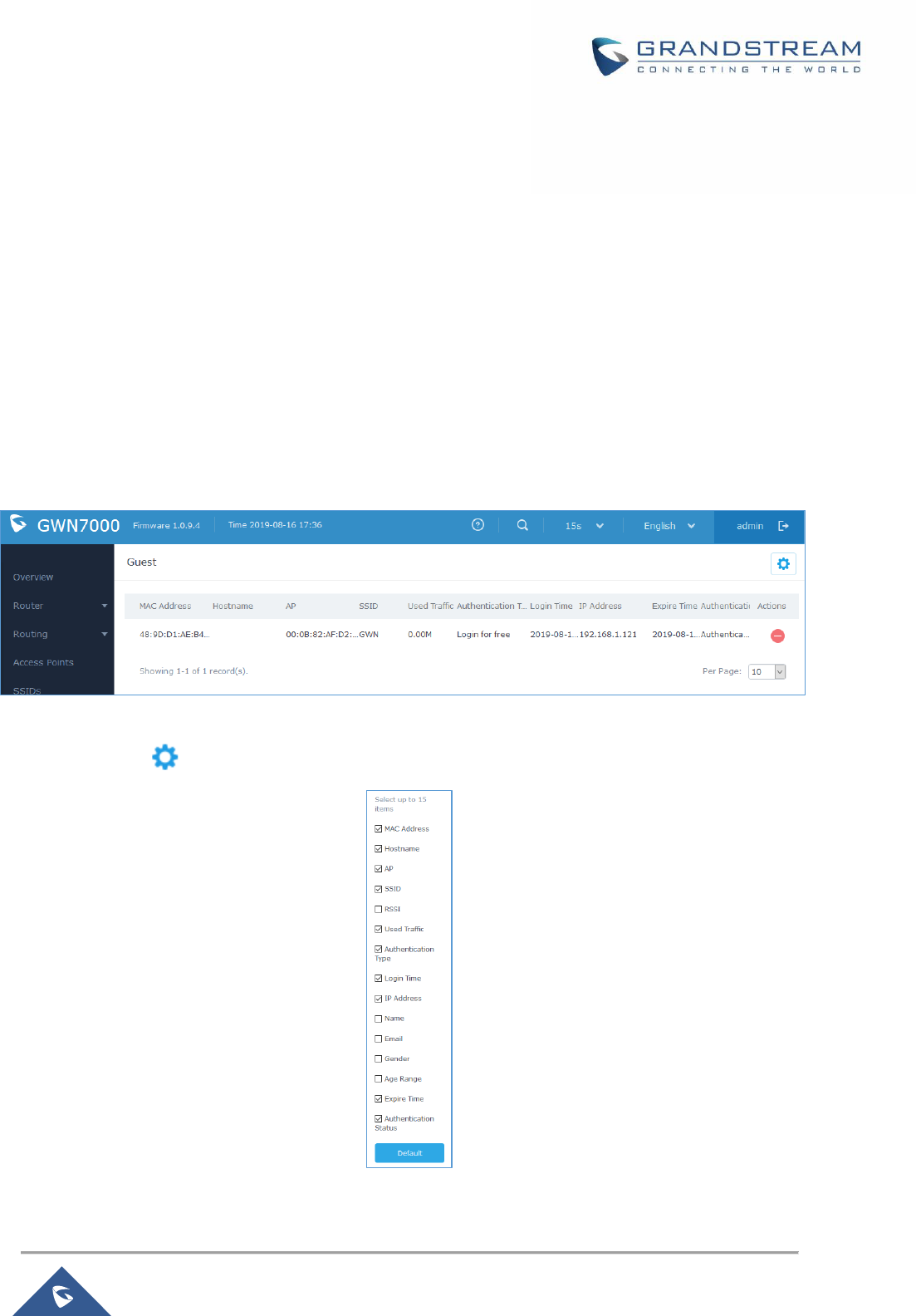
P a g e | 123
GWN7000 User Manual
Version 1.0.9.6
CAPTIVE PORTAL
Captive Portal feature on GWN76XX AP helps to define a Landing Page (Web page) that will be displayed
on Wi-Fi clients’ browsers when attempting to access Internet. Once connected to a GWN76XX AP, Wi-Fi
clients will be forced to view and interact with that landing page before Internet access is granted.
The Captive Portal feature can be configured from the GWN7000 Web page under “Captive Portal”.
The page contains three tabs: Policy, Files and Clients.
Guest
This section lists the clients connected or trying to connect to Wi-Fi via Captive Portal.
Figure 72: Captive Portal – Guest Page
Users can press button to customize items to display on the page. Following items are supported:
Figure 73: Captive Portal - Guest Page - Select Items
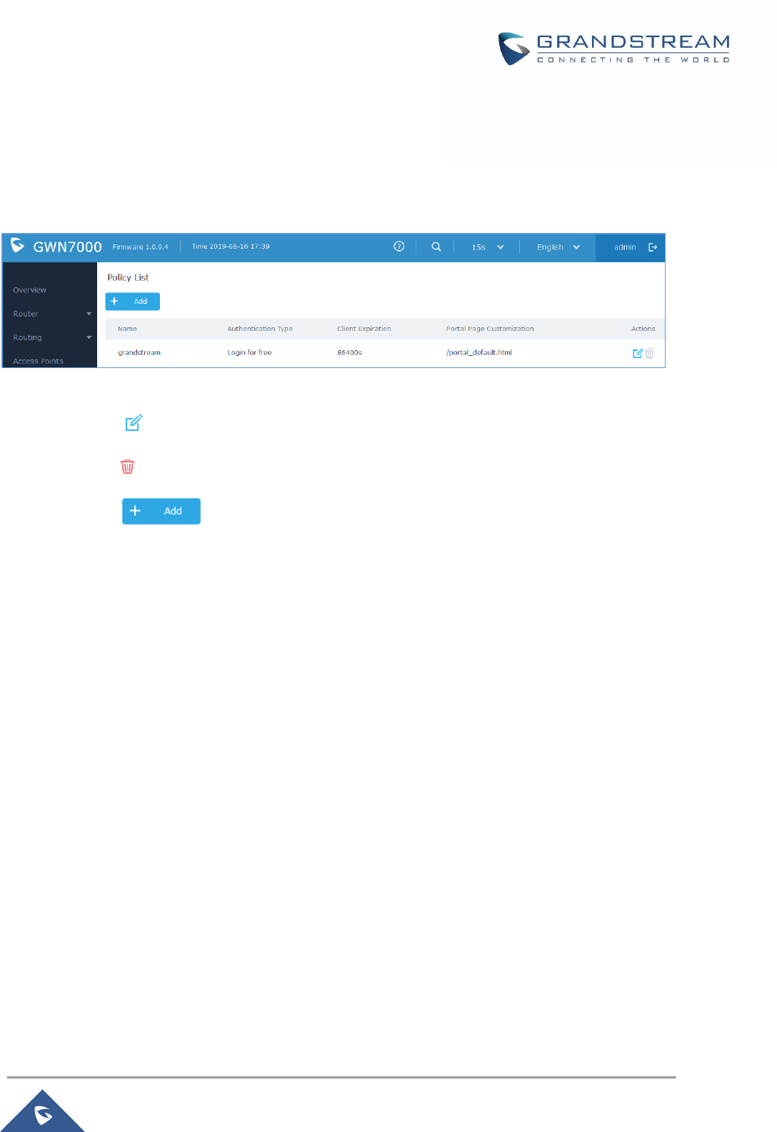
P a g e | 124
GWN7000 User Manual
Version 1.0.9.6
Policy List
Users can customize a portal policy in this page.
Figure 74: Captive Portal - Policy List
• Click on to edit the policy.
• Click on to delete the policy.
• Click on to add a policy.
The policy configuration page allows adding multiple captive portal policies which will be applied to SSIDs
and contains options for different authentication types a splash page that can be easily configured as
shown on the next section.
Administrator can use an internal or external splash page.

P a g e | 125
GWN7000 User Manual
Version 1.0.9.6
Figure 75: Add a New Policy
Internal Splash Page
Below table lists the items policy add page configures.

P a g e | 126
GWN7000 User Manual
Version 1.0.9.6
Table 42: Captive Portal – Policy List – Splash Page is “Internal”
Field
Description
Name
Enter the name of the Captive Portal policy
Splash Page
Select Splash Page type, Internal or External.
Authentication Type
Following types of authentication are available:
• Login for free: when choosing this option, the landing page feature will not
provide any type of authentication, instead it will prompt users to accept the
license agreement to gain access to internet.
• RADIUS Server: Choosing this option will allow users to set a RADIUS
server to authenticate connecting clients.
• Social Login Authentication: Choosing this option will allow users to
enable authentication Facebook or Twitter or WeChat.
• Vouchers: Choose this page when using authentication via Vouchers.
• Login with Password: Choose this page when using authentication via a
password.
Expiration
Configures the period of validity, after the valid period, the client will be
re-authenticated again.
If Authentication Type is set to “RADIUS Authentication”
RADIUS Server
Address
Fill in the IP address of the RADIUS server.
RADIUS Server Port
Set the RADIUS server port, the default value is 1812.
RADIUS Server Secret
Fill in the key of the RADIUS server.
RADIUS Authentication
Method
Select the RADIUS authentication method, 3 methods are available: PAP, CHAP
and MS-CHAP.
If Authentication Type is set to “Social Login Authentication”
WeChat
Check to enable/disable WeChat Authentication
Shop ID
Fill in the Shop ID that offers WeChat Authentication.
APP ID
Fill in the APP ID provided by the WeChat in its web registration page
Secret Key
Set the key for the portal, once clients want to connect to the Wi-Fi, they should
enter this key.
Facebook
Check to enable/disable Facebook Authentication
Facebook App ID
Fill in the Facebook App ID.
Facebook APP Key
Set the key for the portal, once clients want to connect to the Wi-Fi___33, they
should enter this key.

P a g e | 127
GWN7000 User Manual
Version 1.0.9.6
Twitter
Check this box to enable Twitter Authentication.
Force to Follow
If checked, users need to Follow owner before been authenticated.
Owner
Enter the app Owner to use Twitter Login API.
This field appears only when Force to Follow is checked.
Consumer Key
Enter the app Key to use Twitter Login API.
Consumer Secret
Enter the app secret to use Twitter Login API.
For all Authentication Types
Use Default Portal
Page
If checked, the users will be redirected to the default portal page once
connected to the GWN.
If unchecked, users can manually select which Portal Page to use from Portal
Page Customization drop-down list.
Portal Page
Customization
Select the customized portal page (if “Use Default Portal Page” is unchecked).
• /facebook.html
• /password_auth.html
• /portal_default.html
• /portal_pass.html
• /portal_tip.html
• /social_auth.html
• /status.html
• /twitter.html
• /twitter_website.html
• /vouchers_auth.html
• /wechat.html
Landing Page
Choose the landing page, 2 options are available:
• Redirect to the Original URL.
• Redirect to External Page.
Redirect External Page
URL Address
Once the landing page is set to redirect to external page, user should set the
URL address for redirecting.
This field appears only when Landing Page is set to “Redirect to an External
Page”.
Enable Daily Limit
If enabled, captive portal will limit user connection by times of one day.
Failsafe Mode
If checked, AP will grant access to STA if AP can’t reach to external
authentication server.
This option is available only when Authentication Type is set to “RADIUS
Server” or “Vouchers”.
P a g e | 128
GWN7000 User Manual
Version 1.0.9.6
Enable HTTPS
Check to enable/disable HTTPS service.
Notes:
1. If Facebook authentication is configured, you will need to log in your Facebook account of
https://developers.facebook.com/apps , and set the OAuth redirect to :
https://cwp.gwn.cloud:8443/GsUserAuth.cgi?GsUserAuthMethod=3
2. If Twitter authentication is configured, you will need to log in your Twitter account of
https://apps.twitter.com/app, and set the callback URLs to:
http://cwp.gwn.cloud:8080/GsUserAuth.cgi
External Splash Page
Table 43: Captive Portal – Policy List – Splash Page is “External”
Field
Description
Name
Enter the name of the Captive Portal policy
Splash Page
Select to either use Internal or External Splash Page.
Platform
Select which external captive portal platform to use:
• Linkyfi Platform (https://www.avsystem.com/products/linkyfi)
• Purple Platform (https://purple.ai/)
• Universal Platform (when using other external captive portal
platforms)
External Splash Page
URL
Enter the External Splash Page URL, and make sure to enter the
pre-authentication rules request by the external portal platform in the
pre-authentication configuration option.
RADIUS Server
Address
Fill in the IP address of the RADIUS server.
RADIUS Server Port
Set the RADIUS server port, the default value is 1812.
RADIUS Server Secret
Fill in the key of the RADIUS server.
RADIUS Accounting
Server Address
Configures the address for the RADIUS accounting server.
RADIUS Accounting
Server Port
Configures RADIUS accounting server listening port (default is 1813).
RADIUS Accounting
Server Secret
Enter the secret password for client authentication with RADIUS accounting
server.
Accounting Update
Interval
Enter Update Interval for RADIUS Accounting Server. The interval unit can be
set by seconds, minutes, hours or days.
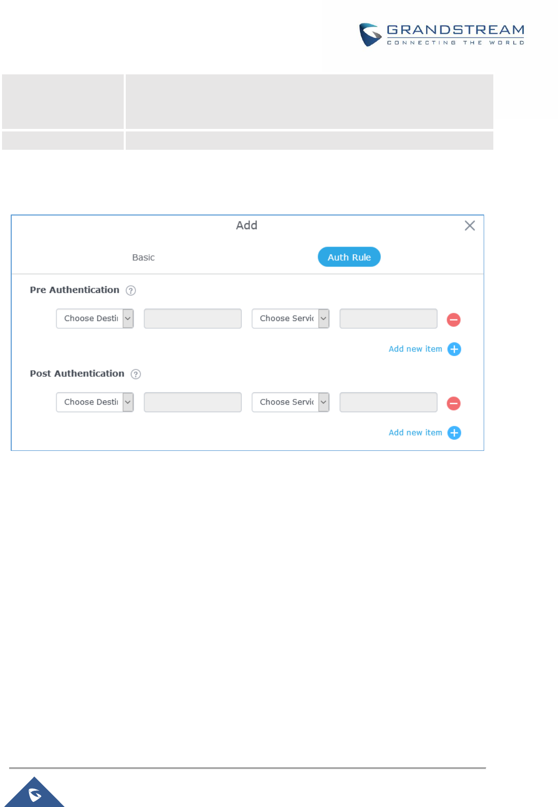
P a g e | 129
GWN7000 User Manual
Version 1.0.9.6
RADIUS NAS ID
Enter RADIUS NAS ID.
This field appears only when Platform is set to “Linkyfi Platform” or “Universal
Platform”.
Redirect URL
Specify URL where to redirect clients after authentication.
In case social media authentication is used, the user needs to allow some traffic between the AP and
social medial platforms (Facebook API as example) to send authentication credentials and receive reply,
this traffic can be allowed using the Authentication rules which are explained below.
Figure 76: Authentication rules
Pre-Authentication Rules
Using this option, users can set rules to match traffic that will be allowed for connected Wi-Fi users before
authentication process. This can be needed for example to setup Facebook authentication where some
traffic should be allowed to Facebook server(s) to process the user’s authentication. Or simply to be used
to allow some type of traffic for unauthenticated users.
Post-Authentication Rules
On the other hand, post authentication rules are used to match traffic that will be banned for Wi-Fi clients
after authentication. As an example, if you want to disallow connected Wi-Fi clients to issue Telnet or SSH
traffic after authentication then you can set post authentication rules to match that traffic and once a
connected client passes the authentication process they will be banned from issuing telnet and SSH
connections.
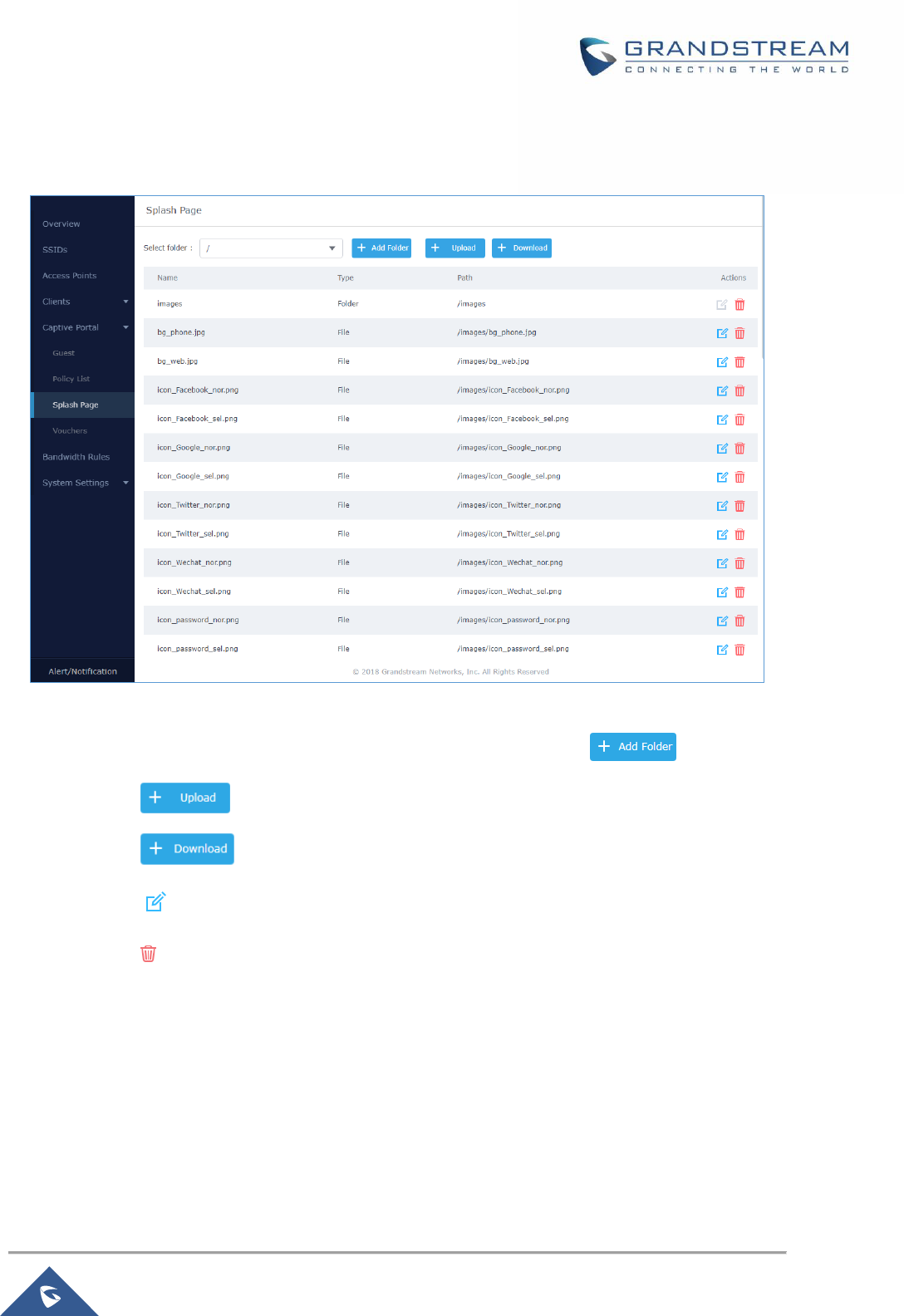
P a g e | 130
GWN7000 User Manual
Version 1.0.9.6
Splash Page
Files configuration page allows users to view and upload HTML pages and related files (images…).
Figure 77: Captive Portal – Splash Page
User can add folder in corresponding folder by selecting the folder and click on .
• Click on to upload a file from local device.
• Click on to download the files in Captive Portal folder.
• Click on to edit the corresponding file, in another word, to replace the file with a new one.
• Click on to delete the file.

P a g e | 131
GWN7000 User Manual
Version 1.0.9.6
Vouchers
Voucher Feature Description
Voucher feature will allow clients to have internet access for a limited duration using a code that is
randomly generated from GWN controller.
As an example, a coffee shop could offer internet access to customers via Wi-Fi using voucher codes that
can be delivered on each command. Once the voucher expires the client can no longer connect to the
internet.
Note that multiple users can use a single voucher for connection with expiration duration of the voucher
that starts counting after first successful connection from one of the users that are allowed.
Another interesting feature is that the admin can set data bandwidth limitation on each created voucher
depending on the current load on the network, users’ profile (VIP customers get more speed than regular
ones...etc.) and the internet connection available (fiber, DSL or cable…etc.) to avoid connection
congestion and slowness of the service.
Each created voucher can be printed and served to the customers for usage, and the limit is 1000
vouchers.
The usage of voucher feature needs to be combined with captive portal that is explained after this section,
in order to have the portal page requesting clients to enter voucher code for authentication.
Voucher Configuration
To configure/create vouchers for clients to use, follow below steps:
1. On controller web GUI, navigate under “Captive Portal → Vouchers”
2. Click on button in order to add a new voucher.
3. Enter voucher details which are explained on the next table.
4. Press save to create the voucher(s).
Notes:
• Users can specify how many vouchers to generate which have the same profile, this way the GWN
will generate as many vouchers as needed which do have the same settings avoiding creating
them one by one.
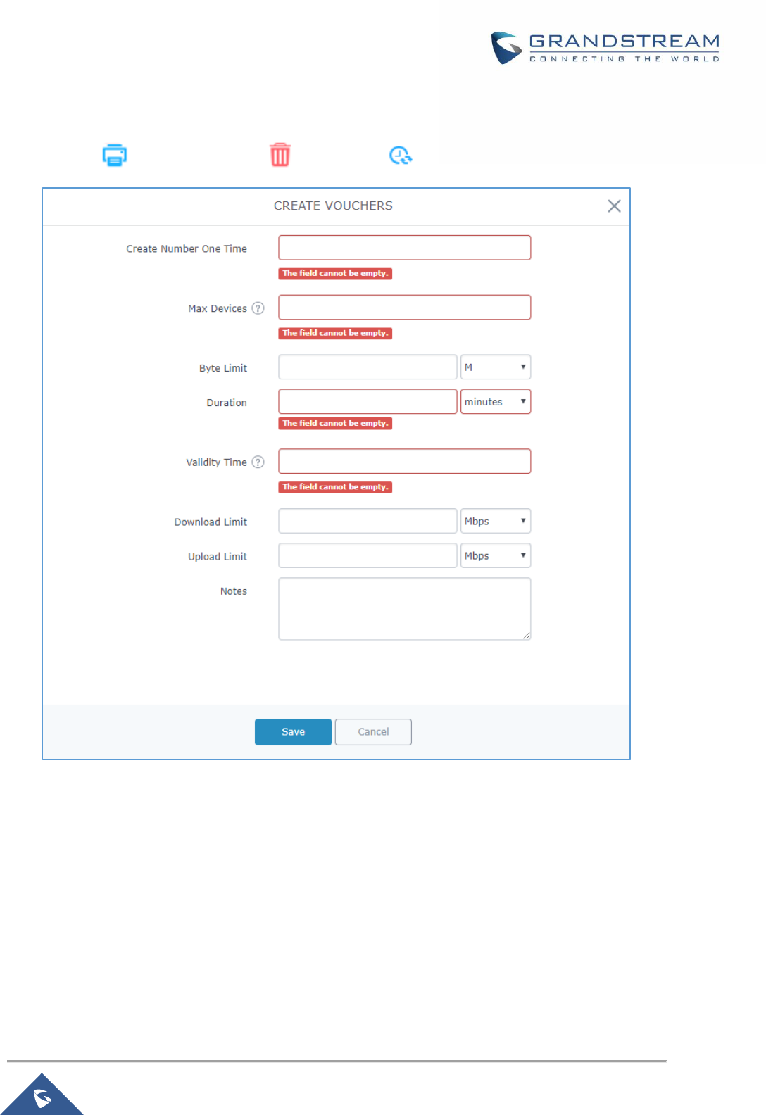
P a g e | 132
GWN7000 User Manual
Version 1.0.9.6
• The admin can verify the status of each vocoder on the list (In use, not used, expired …etc.).
• Press to print the voucher, to delete it or to renew the voucher.
Figure 78: Add Voucher Sample
The below figure shows the status of the vouchers after GWN randomly generates the code for each one.
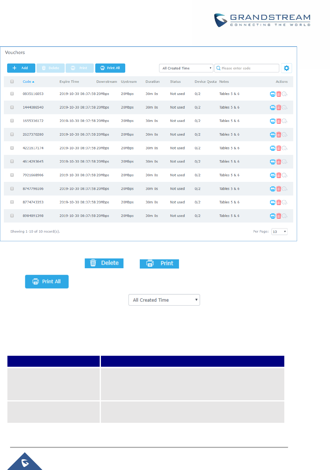
P a g e | 133
GWN7000 User Manual
Version 1.0.9.6
Figure 79: Vouchers List
Users can click on buttons and to delete and print multiple vouchers or
click button to print all vouchers at once.
Also, users can use the drop-down list filter to filter the vouchers that where
created at specific date-time.
The following table summarizes description for voucher configuration parameters:
Table 44: Voucher Parameters
Field
Description
Create Number One Time
Specify how many vouchers to generate which will have same
profile/settings (duration, bandwidth and number of users).
Valid range: 1 – 1000.
Max Devices
Specify how many users can use same voucher.
Valid range: 1 – 5.

P a g e | 134
GWN7000 User Manual
Version 1.0.9.6
Duration
Specify the duration after which the voucher will expire, and clients
will be disconnected from internet.
Note: in case or multiple users, the duration will start counting after
first user starts using the voucher.
Validity Time
Set the validity period of credentials, limited to 1-365 integer. The
unit is day.
Download Limit
Set the downstream bandwidth speed limit (in Kbps or Mbps).
Upload Limit
Set the upstream bandwidth speed limit (in Kbps or Mbps).
Notes
Notes for the admin when checking the list of vouchers.
Using Voucher with GWN Captive Portal
In order to successfully use the voucher feature, users will need to create a captive portal in order to
request voucher authentication codes from users before allowing them access to internet. More details
about captive portal will be covered on next section but for voucher configuration please follow below
steps.
1. Go under “Captive Portal → Captive portal” menu.
2. Press in order to add new captive portal policy.
3. Set the following parameters as shown on the screenshot for basic setup then save and apply.
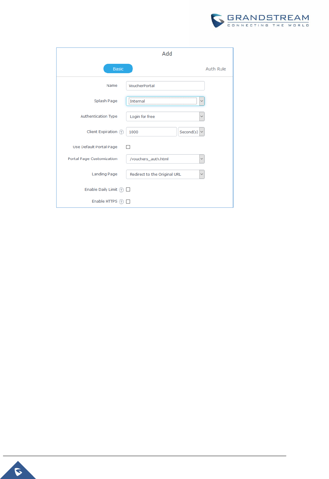
P a g e | 135
GWN7000 User Manual
Version 1.0.9.6
Figure 80: Captive Portal with Voucher authentication
Then go under your SSID configuration page and enable the generated captive portal under Wi-Fi settings
tab.
P a g e | 136
GWN7000 User Manual
Version 1.0.9.6
BANDWIDTH RULES
The bandwidth rule is a GWN7000 feature that allows users to limit bandwidth utilization per SSID or client
(MAC address or IP address).
This option can be configured from the GWN7000 router web UI under “Bandwidth Rules”.
Click to add a new rule, the following table provides an explanation about different options
for bandwidth rules.
Table 45: Bandwidth Rules
Field
Description
Enable
Enable/Disable the Bandwidth rule.
SSID
Select which SSID will be affected by the bandwidth rule limitation.
Range Constraint
Choose the type of rule to be applied on bandwidth utilization from the
dropdown list, three options are available:
• Per-SSID: Set a bandwidth limitation on the SSID level.
• Per-Client: Set a bandwidth limitation per Client.
• MAC: Set a bandwidth limitation per MAC address.
• IP Address: Set a bandwidth limitation per IP address.
MAC
Enter the MAC address of the device to which the limitation will be
applied, this option appears only when MAC type is selected.
IP address
Enter the IP address of the device to which the limitation will be applied,
this option appears only when IP Address type is selected.
Enable Schedule
Enable this option to assign a schedule for the bandwidth rule.
Upload Limit
Specify the limit for the upload bandwidth using Kbps or Mbps.
Download Limit
Specify the limit for the download bandwidth using Kbps or Mbps.
The following figure shows an example of MAC address rule limitation.
P a g e | 137
GWN7000 User Manual
Version 1.0.9.6
Figure 81: MAC Address Bandwidth Rule
The following figure shows examples of bandwidth rules:
Figure 82: Bandwidth Rules
Note:
The same settings for bandwidth management are available from the following menus:
Per-Client
Navigate on the web GUI under “Clients→Edit→Bandwidth Rules” where you can set the Upstream and
Downstream rate in Mbps.

P a g e | 138
GWN7000 User Manual
Version 1.0.9.6
WEBSITE BLOCKING
Website blocking is a feature that allows the system administrator to download filter lists or create their
own filter lists to block DNS queries to some domains. These lists can be used to block adware sites,
malware sites, and can be used to block popular social media websites (Facebook, YouTube...etc).
The administrator is able to apply this feature to any combination of network groups or clients.
In order to configure website blocking policy follow the next steps:
Create Blackhole Policy
First, you need to create blocking policies on which you specify the list of domains to be blocked or allowed
or specify URL from which download full list of unwanted bad domains such as malware domains.
To do so go under “System Settings → Website Blocking → Blackhole policy” and press
to create a new policy.
Figure 83: Create Blackhole Policy
P a g e | 139
GWN7000 User Manual
Version 1.0.9.6
On the figure above, we set the link from which the GWN will go and fetch all domain names that would be
considered as bad domains and blocked.
After this, save and apply the changes and the new policy will be displayed along the existing ones.
Figure 84: Blackhole Policy List
Assign Blackhole Policy to Network Groups
Now, that we have created a policy. It’s time to assign it to a network group or client. To assign a blocking
policy to a network group go under “System Settings → Website Blocking → Network Group
Blackhole” and press add .

P a g e | 140
GWN7000 User Manual
Version 1.0.9.6
Figure 85: Network Group Blackhole
Give the network group blackhole a name, then check the box to enable it, after that set a binding port for
the blackhole (range valid from 1025 to 65535) and select which policy(s) to apply to which network
group(s).
Note: A network group can be assigned to only one network group blackhole, thus you need to apply all
required blocking policies to a specific network group to its network group blackhole policy.
Press save and apply and the changes, and now all clients within network group0 are banned (protected)
from malware websites.
Assign Blackhole Policy to Clients
Another possibility, it to create client based blackhole(s) on which the policy will apply to specific client(s)
defined by a CACL (Client Access Control List) and on this case, the admin is left with the choice to either
force the network group policy on this client along with its specific policy or ignore the network group
definition and keep only the client-based policy.
For example, with the configuration above and while maintaining the blocking of malware websites on
P a g e | 141
GWN7000 User Manual
Version 1.0.9.6
group0, we want to block Facebook access from some specific clients defined on access list 1.
We assume that we have already created a blocking policy under “System Settings → Website blocking
→ Blackhole Policy” to set Facebook.com as bad domain.
Next, go under “Clients → Client Access” to define the list of clients to whom the policy will apply.
Figure 86: Clients ACL
Finally, and in order realize the scenario above, go under “System Settings → Website Blocking →
Client Blackhole” and click on .
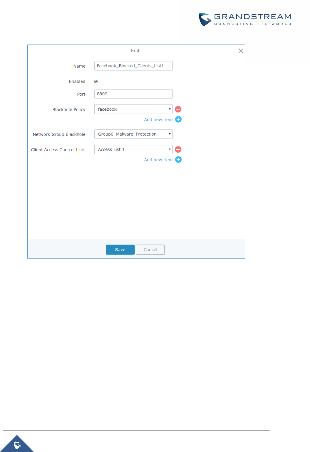
P a g e | 142
GWN7000 User Manual
Version 1.0.9.6
Figure 87: Client Blackhole Configuration
On this case, we can either force the network group policy that was created for the full group0 along with
the new blackhole policy (Facebook) or ignore it and assign only the Facebook blocking policy to the
clients specified on list1.

P a g e | 143
GWN7000 User Manual
Version 1.0.9.6
MAINTENANCE AND TROUBLESHOOTING
GWN7000 offers multiple tools and options for maintenance and debugging to help further troubleshooting
and monitoring the GWN7000 resources.
Maintenance
Maintenance page can be accessed from GWN7000 WebGUI→System Settings→Maintenance.
Maintenance page includes different tabs: Basic, Upgrade, Access, Syslog and Logserver.
Basic
Table 46: Maintenance - Basic
Rebind Protection
Anti-domain name hijacking protection.
If enabled, when the address returned by the superior DNS is a private LAN
address, it will be regarded as a domain name hijacking, thus discarding the
analytical result.
If disabled, the analytical result will not be discarded.
Web WAN Access
Enable the web WAN access. By default, it’s disabled
Web HTTP Access
Enable the web HTTP Access. By default, it’s disabled.
Web HTTPS Port
Specifies the HTTPS port.
By default, is 443.
Country
Select the country from the drop-down list.
Time Zone
Configure time zone for the GWN7000.
Please reboot the device to take effect.
NTP Server
Configure the IP address or URL of the NTP server, the device will obtain
the date and time from the configured server.
Date Display Format
Change the Date Display Format, three options are possible YYYY/MM/DD,
MM/DD/YYYY and DD/MM/YYYY
Reboot Schedule
Select the pre-configured schedule (System Settings → Schedule), once a
schedule is selected, then the network will not be working for a while (reboot
duration during the scheduled reboot duration.

P a g e | 144
GWN7000 User Manual
Version 1.0.9.6
Upgrade
Table 47: Maintenance - Upgrade
Authenticate Config File
Authenticate configuration file before acceptance. Default is disabled.
XML Config File Password
Enter the password for encrypting the XML configuration file using
OpenSSL.
The password is used to decrypt the XML configuration file if it is encrypted.
Upgrade Via
Specify uploading method for firmware and configuration. 3 options are
available: HTTP, HTTPS and TFTP.
Firmware Server
Configure the IP address or URL for the firmware upgrade server.
Config Server
Configure the IP address or URL for the configuration file server.
Check Update on Boot
Choose whether to enable or disable automatic upgrade and provisioning
after reboot. Default is disabled.
Automatic Upgrade Check
Interval(m)
Specify the time period to check for firmware upgrade (in minutes).
Reboot
Click on Reboot button to reboot the device
Download Configuration
Click on Download to download the device’s configuration file.
Upgrade Now
Click on Upgrade, to launch firmware/config file provisioning.
Please make sure to Save and Apply changes before clicking on Upgrade.
Factory Reset
Click on Reset to restore the GWN7000 as well as all online GWN76xx units
to factory default settings
Access
Table 48: Maintenance - Access
Current Administrator
Password
Enter the current administrator password
New Administrator
Password
Change the current password. This field is case sensitive with a maximum
length of 32 characters.
Confirm New
Administrator Password
Enter the new administrator password one more time to confirm.
User Password
Configure the password for user-level Web GUI access. This field is case
sensitive with a maximum length of 32 characters.
User Password
Confirmation
Enter the new User password again to confirm.
P a g e | 145
GWN7000 User Manual
Version 1.0.9.6
Syslog
Table 49: Maintenance - Syslog
Syslog Server
Enter the IP address or URL of Syslog server. Please reboot the GWN7000
to take effect.
Syslog Level
Select the level of Syslog, 5 levels are available: None, Emergency, Alert,
Critical, Error, Warning, Notice, Information and Debug.
Please reboot the GWN7000 to take effect.
Logserver
The logserver page allows the user to configure syslog server on GWN7000 in order to save log messages
on connected external USB drive.
First connect a USB drive to the Access point, then configure the parameters and make sure to start the
server in order to collect messages from devices sending syslog to GWN.
Following table gives description for configuration parameters of GWN Logserver:
Option
Description
Enable WAN Firewall Rule
Enable WAN Firewall rules to allow incoming syslog messages to the
router.
Logrotate File Size
Select the size of file to trigger rotation, if left empty, then the router will use
only the Logrotate frequency rules to trigger rotation.
Logrotate File Count
Select the Maximum number of rotates files to keep. Default is 56 files.
Logrotate Mode
Choose the time rotation frequency mode (default every 3 hours).
• Every X hours (0-23)
• Every X Minutes (0-59).
• X hour of day (0-23).
• X day of week (Sunday-Saturday) + X hour of day (0-23).
Hours
Enter the number of hours period after which trigger file rotation.
Minutes
Enter the number of Minutes period after which trigger file rotation.
Hour of the day
Enter the hour of day at which trigger file rotation.
Day of the week
Enter Day of the week + hour of day, at which trigger file rotation.
Devices
Select the path (a USB partition) to store collected logs. Required.
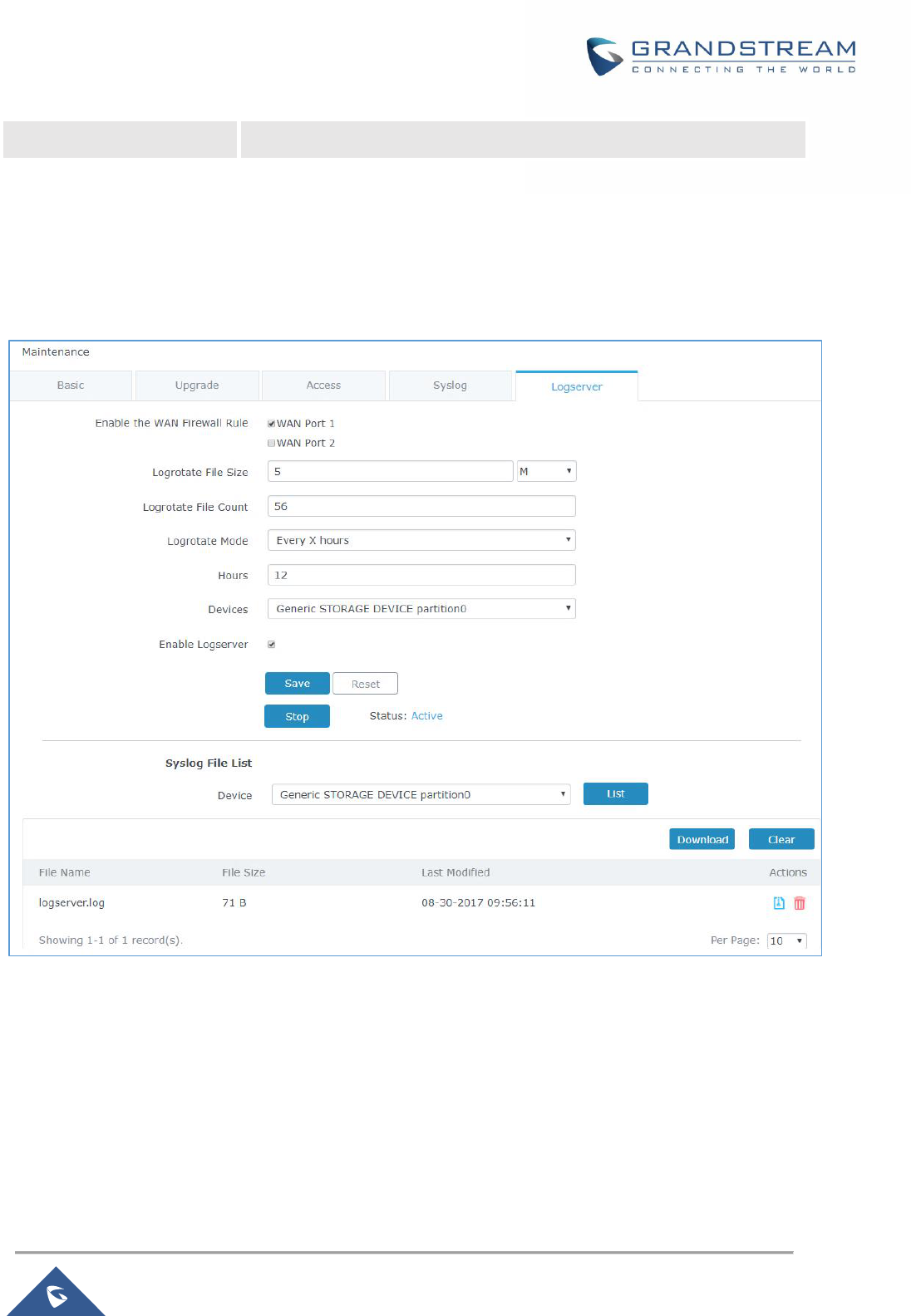
P a g e | 146
GWN7000 User Manual
Version 1.0.9.6
Enable Logserver
Enables the logserver
After setting up the logserver and saving the settings, users need to connect a USB external storage and
press Start button in order to start collecting logs.
All log messages from all devices will be put on one single file, and the router will keep rotating and
creating new files based on the configured rotation policy.
Figure 88: Logserver Configuration
Debug
Many debugging tools are available on GWN7000’s WebGUI to check the status and troubleshoot
GWN7000’s services and networks.
Debug page offers 4 tabs: Capture, Ping/Traceroute, Syslog and Connection Table.
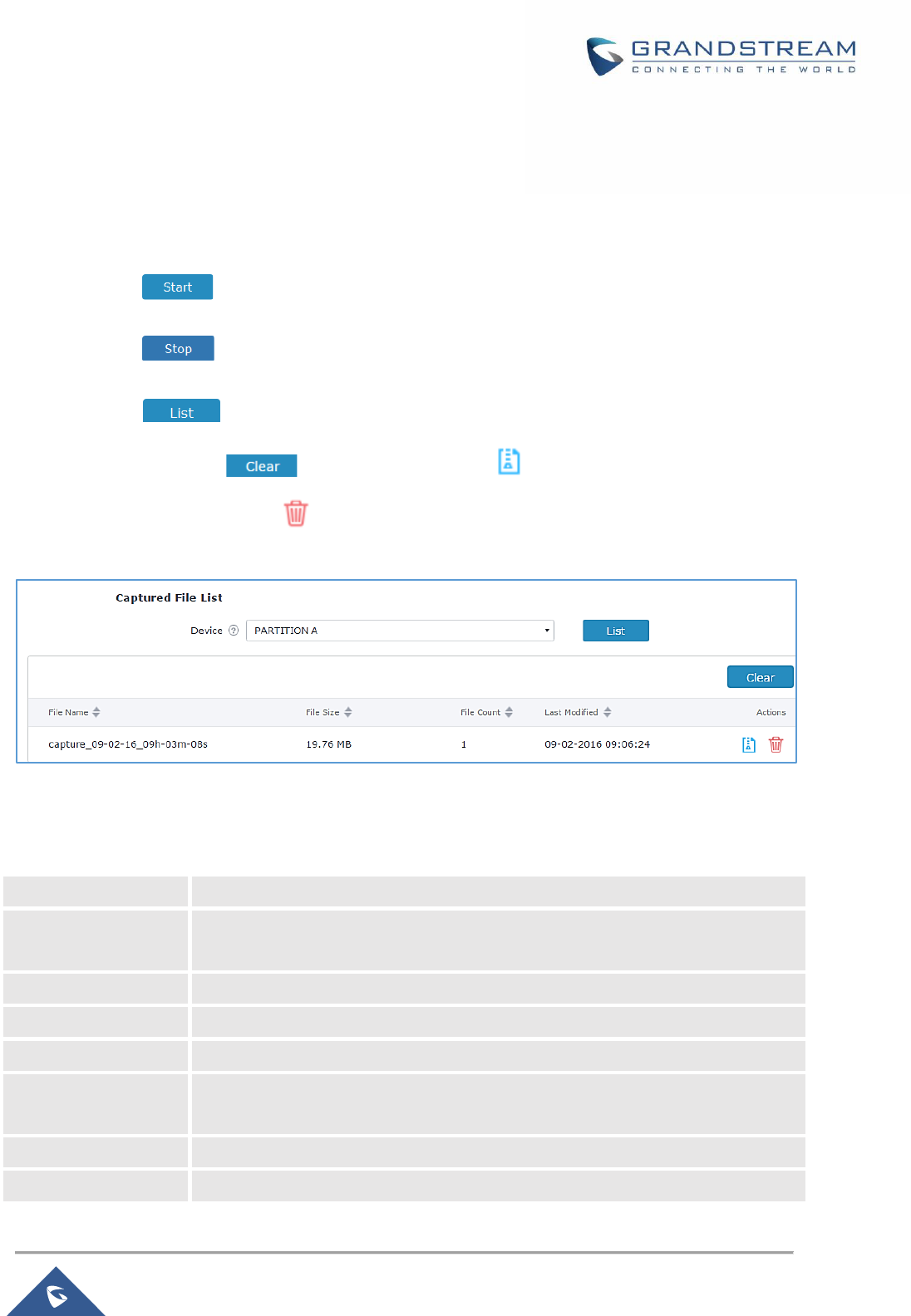
P a g e | 147
GWN7000 User Manual
Version 1.0.9.6
Capture
This section is used to capture packet traces from the GWN7000 interfaces (WAN ports and network
groups) for troubleshooting purpose or monitoring...
It is needed to plug an USB storage device to one of the USB ports on the back of the GWN7000.
• Click on to start capturing on a certain device plugged to the USB port.
• Click on to stop the capture.
• Click on to show the captured files on a chosen device, and the capture files details
will appear, click on to delete all files, click on next to a capture file to download it
on a local folder, or click on to delete it.
Figure 89: Capture Files
The below table will show different fields used on capture page
Table 50: Debug-Capture
File Name
Enter the name of the capture file that will be generated.
Interface
Choose an Interface (WAN port1 or 2, or a network group) from where to begin
the capture.
Device
Choose a device plugged to USB port to save the capture once started.
File Size
Set a File size that the capture will not exceed (Optional field).
Rotate Count
Set a value for rotating captures (Optional Field).
Direction
Choose if you want to get all traffic or only outgoing or incoming to the choses
interface.
Source Port
Set the Source Port to filter capture traffic coming from the defined source port.
Destination Port
Set the Destination Port to filter capture traffic coming from the defined port.
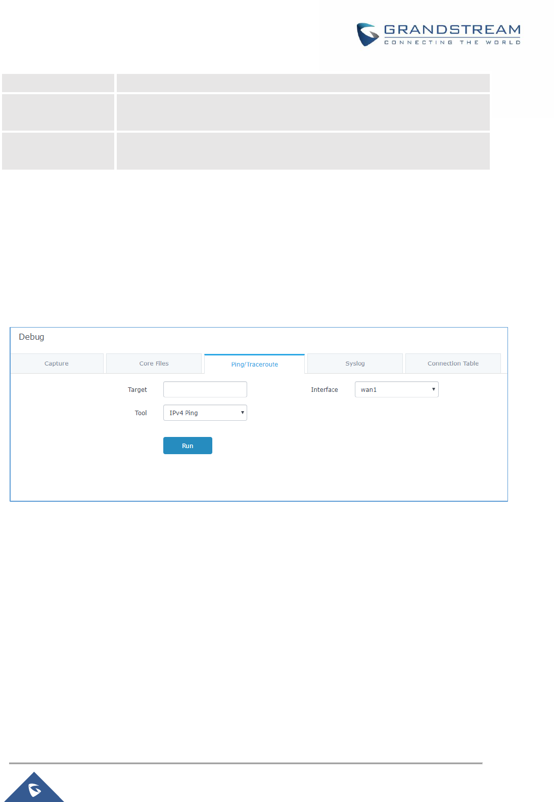
P a g e | 148
GWN7000 User Manual
Version 1.0.9.6
Source IP
Set the Source IP to filter capture traffic coming from the defined source IP.
Destination IP
Set the Destination IP to filter capture traffic coming from the defined destination
IP.
Protocol
Choose ALL or a specific protocol to capture (IP, ARP, RARP, TCP, UDP, ICMP,
IPv6)
Ping/Traceroute
Ping and Traceroute are useful debugging tools to verify reachability with other clients across the network
(WAN or LAN). The GWN7000 offers both Ping and Traceroute tools for IPv4 and IPv6 protocols.
To use these tools, go to GWN7000 WebGUI→System Settings→Debug and click on Ping/Traceroute.
Figure 90: IP Ping
1. Type in the destination’s IP address/domain name in Target field.
2. Select from which interface to issue the Ping/Traceroute from Interface dropdown list.
3. Next to Tool choose from the dropdown menu:
• IPv4 Ping for an IPv4 Ping test to Target
• IPv6 Ping for an IPv6 Ping test to Target
• IPv4 Traceroute for an IPv4 Traceroute to Target
• IPv6 Traceroute for an IPv6 Traceroute to Target
4. Click on Run.
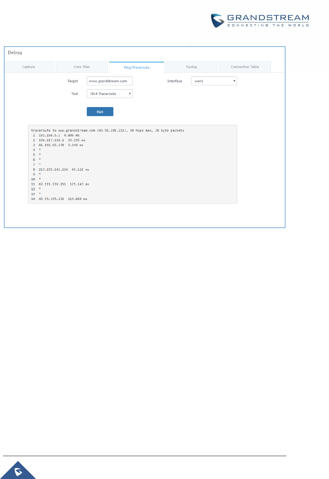
P a g e | 149
GWN7000 User Manual
Version 1.0.9.6
Figure 91: Traceroute
Syslog
GWN7000 supports dumping the syslog information to a remote server under Web GUI→System
Settings→Maintenance→Syslog.
Enter the syslog server hostname or IP address and select the level for the syslog information. Five levels
of syslog are available: None, Debug, Info, Warning, and Error.
Syslog messages are also displayed in real time under Web GUI→System Settings→Debug→Syslog.
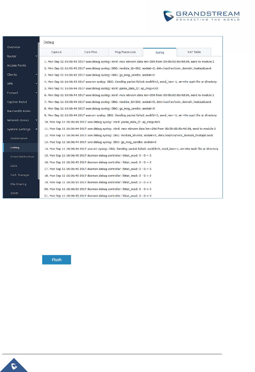
P a g e | 150
GWN7000 User Manual
Version 1.0.9.6
Figure 92: Syslog
Connection Table
NAT table is updated dynamically on GWN7000’s WebGUI, to check the NAT table go to System
Settings→Debug→Connection Table.
Users could press button to clear all entries.
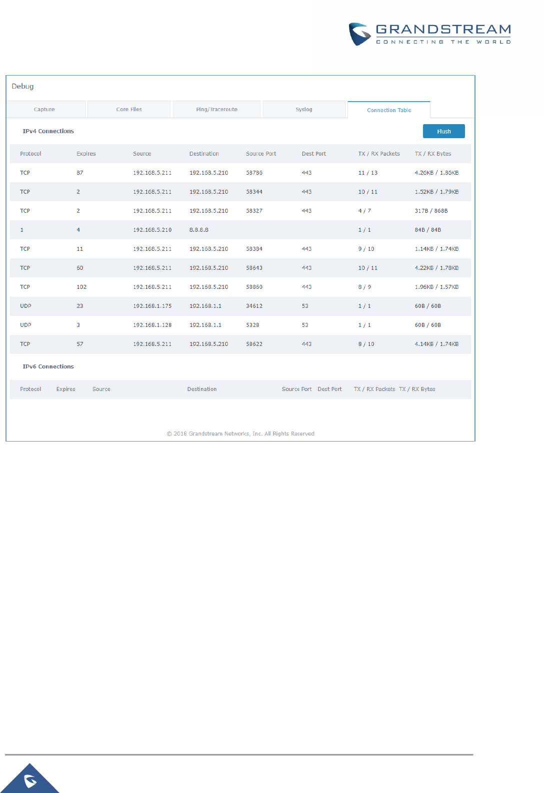
P a g e | 151
GWN7000 User Manual
Version 1.0.9.6
Figure 93: Connection Table
Email/Notification
The Email/Notification page allows the administrator to select a predefined set of system events and to
send notifications upon the change of the set events.
P a g e | 152
GWN7000 User Manual
Version 1.0.9.6
Figure 94: Email settings
Table 51: Email Setting
Filed
Description
Enable Email Notification
Once enabled, AP will send related notification email to the the
receivers.
Note: if no event is specified in the Notification page, server will send
an empty mail.
General
From Email Address
Specify the email address of the notification sender. If the address is
not specified, AP will use the SMTP username as a sender.
P a g e | 153
GWN7000 User Manual
Version 1.0.9.6
From Name
Specifies the name of the notification sender.
SMTP Username
Specifies the username to login to the mail server
Email Address
Specifies the email address of the administer where to receive
notifications.
Skip Certificate Validation
Check this box to skip the certificate validation
SMTP Settings
SMTP Host
Configures the SMTP Email Server IP or Domain Name.
SMTP Port
Specifies the Port number used by server to send email.
Receiver Email Address
Specifies the email addresses to receive notifications.
Figure 95: Notification
The following table describe the notifications configuration settings.
Table 52: Email Events
Filed
Description
Enabled
Enable/disable the notification. By default, it’s disabled

P a g e | 154
GWN7000 User Manual
Version 1.0.9.6
Memory Usage
Configures whether to send notification if memory usage is greater than the
configured threshold. By default, it’s disabled.
Memory Usage
Threshold (%)
Specifies the Memory Usage Threshold (%). Must be integer between 1 and 100.
CPU Usage
Configures whether to send notification if CPU usage is greater than the
configured threshold. By default, it’s disabled.
CPU Usage
Threshold (%)
Specifies the CPU Usage Threshold (%). Must be integer between 1 and 100.
WAN1 Usage
Configures whether to send notification if WAN1 usage is greater than the
configured threshold. By default, it’s disabled.
WAN1 Usage
Threshold (%)
Specifies the WAN1 Usage Threshold (%). Must be integer between 1 and 100.
WAN2 Usage
Configures whether to send notification if WAN2 usage is greater than the
configured threshold. By default, it’s disabled.
WAN2 Usage
Threshold (%)
Specifies the WAN2 Usage Threshold (%). Must be integer between 1 and 100.
Firmware upgrade
Configures whether to send notification on firmware upgrade. Default is disabled.
Add/Remove LAN
Configures whether to send notification on LAN added or removed. Default is
disabled.
SSID
Configures whether to send notification if any SSID is enabled. Default is
disabled.
Time Zone Change
Configures whether to send notification on time zone change. Default is disabled.
Administrator
Password Change
Configures whether to send notification on admin password change. Default is
disabled.
AP Offline
Configures whether to send notification when AP going offline. Default is disabled.
Schedule
Users can use the schedule configuration menu to set specific schedule for GWN features while giving the
flexibility to specify the date and time to turn ON/OFF the selected feature.
The Schedule can be used for settings up specific time for Wi-Fi where the service will be active or for LED
schedule or bandwidth rules …etc.
In order to configure a new schedule, follow below steps:
P a g e | 155
GWN7000 User Manual
Version 1.0.9.6
1- Go under “Schedule” and click on Create New Schedule.
Figure 96: Create New Schedule
2- Select the periods on each day that will be included on the schedule and enter a name for the
schedule (ex: office hours).
3- Users can choose to set weekly schedule or absolute schedule (for specific days for example), and if
both weekly schedule and absolute schedules are configured on the same day then the absolute
schedule will take effect and the weekly program will be cancelled for that specific date.
4- Once the schedule periods are selected, click on Save to save the schedule.
The list of created schedules will be displayed as shown on the figure below. With the possibility to edit or
delete each schedule:
P a g e | 156
GWN7000 User Manual
Version 1.0.9.6
Figure 97: Schedules List
LED
GWN76xx Access Points series support also the LED schedule feature. This feature is used to set the
timing when the LEDs are ON and when they will go OFF at customer’s convenience.
This can be useful for example when the LEDs become disturbing during some periods of the day, this way
with the LED scheduler, you can set the timing so that the LEDs are off at night after specific hours and
maintain the Wi-Fi service for other clients without shutting down the AP.
To configure LED schedule, on the GWN76xx AP WebGUI navigate to “System Settings→LEDs”.
Following options are available:
Table 53: LEDs
Field
Description
LEDs Always Off
Configure whether to disable the AP LED dictator
Schedule
Please choose a schedule to assign to LEDs, users can configure
schedules under the menu Schedule
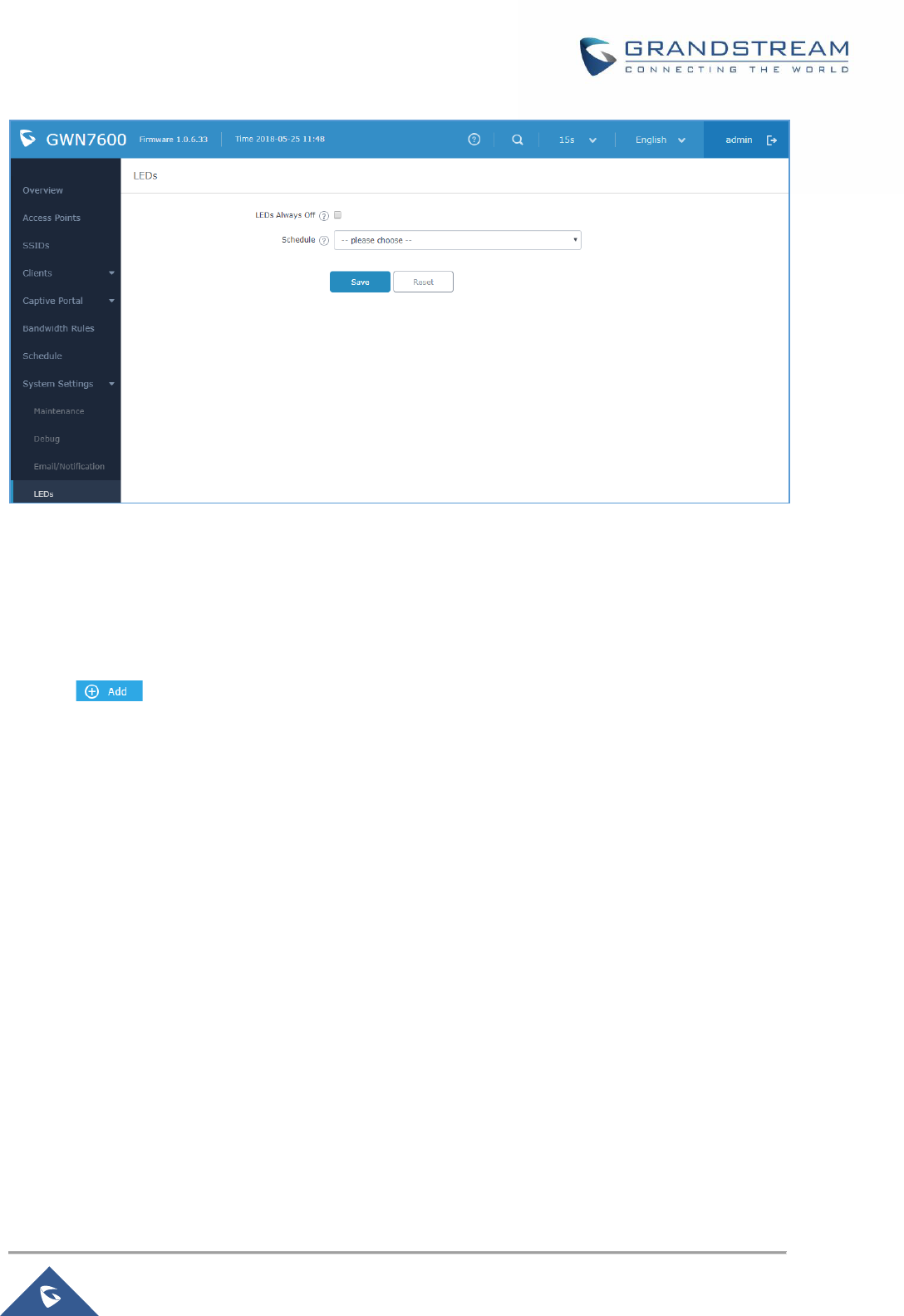
P a g e | 157
GWN7000 User Manual
Version 1.0.9.6
Figure 98: LED Scheduling Sample
File Sharing
The GWN7000 has 2 USB ports that can be also used for file sharing, to enable file sharing on devices
plugged on the USB ports, go to System Settings→File Sharing.
Click on to share a directory and its contents on a device connected to one of the USB ports of
the GWN7000, the following figure will pop up.
P a g e | 158
GWN7000 User Manual
Version 1.0.9.6
Figure 99: Add a New File to Share
Table 54: Add a New File to Share
Share Name
Enter the share name
Path to Share
Choose from the drop menu the path to share.
Access to Share
Choose whether to allow users to Read/Write or Read Only on the shared path.
Comment
Enter a comment for the added shared file.
Share Accessible by
LAN
Choose whether to allow All LANs to access the shared path, restrict access by
selecting only some groups or None.
Edit a Shared Folder by clicking on or delete it by clicking on .
Figure 100: File Share Actions
P a g e | 159
GWN7000 User Manual
Version 1.0.9.6
A device connected to one of the allowed network groups to the shared files can use the following path for
access: \\GWN_Address\Share_Name\ Where GWN_Address is the GWN7000 IP address, and
Share_Name is the Share Name created for the File Share. It is also possible to map a network drive on
Windows, or use a Samba client on Linux machine.
Figure 101: Access File Share
SNMP
GWN7000 supports SNMP (Simple Network Management Protocol) which is widely used in network
management for network monitoring for collecting information about monitored devices.
To configure SNMP settings, go to GWN7000 Web GUI→System Settings→SNMP, this page has two
tabs: Basic and Advanced, refer to the below tables for each tab.
Table 55: SNMP Basic Page
System Location
Set the System Location information, for example: SNMP-Server Lobby GWN.
System Contact
Set the System Contact information, for example: Contact Supervisor_GWN via
extension is 1000.
System Name
Set the System Name information, for example: Supervisor_GWN.
Read-Only
Community for IPv4
Gives the permission for the set community to access and read only to devices in
management information base via IPv4 Protocol.

P a g e | 160
GWN7000 User Manual
Version 1.0.9.6
Read-Write
Community for IPv4
Gives the permission for the set community to access and read/write to devices in
management information base via IPv4 Protocol.
Read-Only
Community for IPv6
Gives the permission for the set community to access and read only to devices in
management information base via IPv6 Protocol.
Read-Write
Community for IPv6
Gives the permission for the set community to access and read/write to devices in
management information base via IPv6 Protocol.
Trap Type
Choose the Trap Type from drop-down menu, 4 options are available: None,
SNMPv1, SNMPv2c and SNMPv2cInforms.
Monitoring Host
Enter the Monitoring Host’s IP/Domain Name (Network Management System
“NMS”)
Monitoring Host Port
Enter the Monitoring Host’s Port (Network Management System “NMS”)
Trap Community
Enter the Trap Community string to authenticate the client against the server.
Table 56: SNMP Advanced Page
SNMP Service
Listening on
Click on to add an SNMP Service Listening on:
• Set the Transport Type: UDPv4, UDPv6, TCPv4 or TCPv6.
• Choose the IP Address from drop-down menu list.
• Set the Port number on which the GWN7000 will listen on.
SNMPv3 Users
Click on to add an SNMPv3 User:
• Set the Username for authentication.
• Choose the Authentication type, 2 options are available: SHA and MD5.
• Set the Authentication Password from Authentication Passphrase.
• Enter the Password again to confirm from Authentication Passphrase
Confirmation.
• Choose the Privacy Protocol, 3 options are available: None, DES and
AES.
• Set the Privacy Passphrase.
• Enter the Privacy Passphrase in Privacy Passphrase Confirmation
field.

P a g e | 161
GWN7000 User Manual
Version 1.0.9.6
User Manager
Under this section, administrator can generate or create user accounts that will be used for VPN
connection authentication, click on in order to create a new user account.
The following table summarizes the configuration parameters:
Table 57: VPN User Parameters
Option
Description
Enabled
Check this option to enable/disable the user account.
PPTP Server
Check this option to enable the user connection to the PPTP server.
Full Name
Enter user full name. When using PPTP it defaults to pptpd.
Username
Enter user Username.
Password
Enter user password.
IPSec Pre-Shared
Key
Set user pre-shared key for authentication.
Enabled PPTP Client
Subnet
Check this option when using PPTP, and enter the client subnet.
Client Subnet
Configured to which subnet this client belongs to (ex: 192.168.1.0/24).
OpenVPN Subnet
Configures OpenVPN user subnet (ex: 192.168.1.0/24).
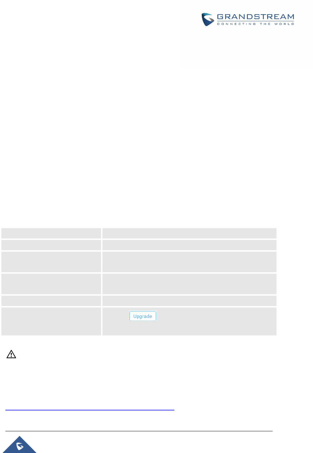
P a g e | 162
GWN7000 User Manual
Version 1.0.9.6
UPGRADING AND PROVISIONING
Upgrading Firmware
The GWN7000 can be upgraded to a new firmware version remotely or locally. This section describes how
to upgrade your GWN7000.
Upgrading via WEB GUI
The GWN7000 can be upgraded via TFTP/HTTP/HTTPS by configuring the URL/IP Address for the
TFTP/HTTP/HTTPS server and selecting a download method. Configure a valid URL for TFTP, HTTP or
HTTPS; the server name can be FQDN or IP address.
Examples of valid URLs:
firmware.grandstream.com/BETA
192.168.5.87
The upgrading configuration can be accessed via Web GUI→Router→Maintenance→Upgrade.
Table 58: Network Upgrade Configuration
Upgrade Via
Choose the firmware upgrade method: TFTP, HTTP or HTTPS.
Firmware Server
Define the server path for the firmware server.
Check/Download New Firmware
and Config at Boot
Allows the device to check if there is a firmware from the configured
firmware server at boot.
Allow DHCP options 66 and 43
override
Configure whether to allow DHCP options 66 and 43 to override
upgrade and provisioning settings.
Automatic Upgrade
Specify the time to check for firmware upgrade (in minutes).
Upgrade Now
Click on button to begin the upgrade. Note that the
device will reboot after downloading the firmware.
--------------------------------------------------------------------------------------------------------------------------------------------
Note:
Please do not interrupt or power cycle the GWN7000 during upgrading process.
--------------------------------------------------------------------------------------------------------------------------------------------
Service providers should maintain their own firmware upgrade servers. For users who do not have
TFTP/HTTP/HTTPS server, some free windows version TFTP servers are available for download from
http://www.solarwinds.com/products/freetools/free_tftp_server.aspx

P a g e | 163
GWN7000 User Manual
Version 1.0.9.6
http://tftpd32.jounin.net
Please check our website at http://www.grandstream.com/support/firmware for latest firmware.
Instructions for local firmware upgrade via TFTP:
1. Unzip the firmware files and put all of them in the root directory of the TFTP server;
2. Connect the PC running the TFTP server and the GWN7000 to the same LAN segment;
3. Launch the TFTP server and go to the File menu→Configure→Security to change the TFTP server's
default setting from "Receive Only" to "Transmit Only" for the firmware upgrade;
4. Start the TFTP server and configure the TFTP server in the GWN7000 web configuration interface;
5. Configure the Firmware Server to the IP address of the PC;
6. Update the changes and reboot the GWN7000.
End users can also choose to download a free HTTP server from http://httpd.apache.org/ or use
Microsoft IIS web server.
Provisioning and backup
The GWN7000 configuration can be backed up locally or via network. The backup file will be used to
restore the configuration on GWN7000 when necessary.
Download Configuration
Download the GWN7000 configurations for restore purpose under Web GUI → Router → Maintenance →
Upgrade
Click on to download locally the configuration file.
Configuration Server
Configuration Server Page allows to provision the GWN7000 by putting the config file on a TFTP/HTTP or
HTTPS server, and set Config Server to the TFTP/HTTP or HTTPS server used in order for the GWN7000
to be provisioned with that config server file.
Reset and Reboot
Used to reboot and reset the device to factory functions under Web GUI→ Router→ Maintenance →
Upgrade by clicking on button.
Will restore all the online GWN76xx as well as well as the GWN7000 itself to factory settings.

P a g e | 164
GWN7000 User Manual
Version 1.0.9.6
EXPERIENCING THE GWN7000 ENTERPRISE ROUTER
Please visit our website: http://www.grandstream.com to receive the most up- to-date updates on firmware
releases, additional features, FAQs, documentation and news on new products.
We encourage you to browse our product related documentation, FAQs and User and Developer Forum
for answers to your general questions. If you have purchased our products through a Grandstream
Certified Partner or Reseller, please contact them directly for immediate support.
Our technical support staff is trained and ready to answer all of your questions. Contact a technical support
member or submit a trouble ticket online to receive in-depth support.
Thank you again for purchasing Grandstream GWN7000 Enterprise Multi-WAN Gigabit VPN Router, it will
be sure to bring convenience and color to both your business and personal life
© 2002-2018 OpenVPN Technologies, Inc.
OpenVPN is a registered trademark of OpenVPN Technologies, Inc.

P a g e | 165
GWN7000 User Manual
Version 1.0.9.6
